Introduction to Nuclear Operations
Under the threat of or in actual nuclear warfare, units in the field must continually evaluate the impact that enemy use of nuclear weapons could have on the conduct of operations. They must be prepared for contingency action to reduce the disruption caused by a nuclear attack.
Casualty-producing levels of fallout can extend to greater distances and cover greater areas than most other nuclear weapon effects. Such fallout levels can, therefore, influence actions on the battlefield for a considerable period. Knowledge and understanding of the radiological contamination aspects discussed in this chapter help the commander determine the advantages and disadvantages of each course of action open to him in the execution of assigned missions.
Fallout areas can be the largest contaminated area produced on the battlefield. There is one important aspect of fallout prediction: Winds aloft, as well as surface winds, determine where fallout will occur. Thus, the actual location of fallout can differ appreciably from that which might be expected from the direction of surface winds.
Fallout particles are often visible during hours of daylight. The arrival and settling of dustlike particles after a nuclear burst should be assumed to indicate the onset of fallout unless monitoring shows no radiation in the area. Any precipitation following a nuclear attack must be regarded as rainout from the nuclear cloud. Rainout will be discussed later in this chapter.
The neutron-induced area is small by comparison with the fallout area produced by the same yield nuclear weapon. It is often contained within the area of greatest destruction and collateral obstacles (tree blowdown, rubble, and fire). Frequently, there will be no need to enter the neutron-induced area. Units should move into neutron-induced areas only when necessary. If units are required to pass through GZ or occupy positions in the immediate vicinity of GZ, the induced radiation is operationally significant. Units will base their entry time and stay time on the radiation level present in the induced area. Induced radiation is discussed in more detail inChapter 7.
The dose rate at any location within a contaminated area does not remain constant. The dose rate decreases with time. Thus, in time a radiation hazard will be of no military significance. The rate at which this decay takes place also varies with time, generally becoming slower as time passes. The decay rate for contamination in an area depends upon many factors. It generally cannot be determined until several series of dose-rate readings are taken for specific locations within the contaminated area. Standard decay conditions are therefore assumed by all units until actual conditions are determined or until higher headquarters directs otherwise.
Nuclear Weapons Effects
To fully appreciate and understand the characteristics of radioactive contamination (fallout) from nuclear detonations, one must first have a basic working knowledge of the origin and nature of these radioactive materials. The overall effects of nuclear weapons depend on the type of weapon, the height of burst (HOB), the distance between the point of detonation and the target, environment in which the weapon is detonated, and the vulnerability of the target.
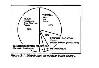
The normal distribution of energy in a low air burst is depicted in Figure 3-1. The primary focus of this chapter centers on only 15 percent of all energy released in a nuclear detonation. That energy is generally referred to as fallout (both initial and residual radiation) and electromagnetic pulse (EMP).
Initial Radiation Effects
Initial nuclear radiation is emitted within the first minute after detonation. For weapons with yields less than approximately 50 kiloton, initial nuclear radiation is usually the governing effect in target planning. It consists primarily of neutrons and gamma rays. Both types of radiation, although different in character, travel considerable distances at the speed of light, and produce casualties.
Residual Radiation Effects
Residual nuclear radiation is that emitted later than one minute after detonation. It consists of fallout, neutron-induced gamma activity (NIGA), and rainout. Residual radiation (fallout) comes from three basic sources: unused fissionable material, fission products, and neutron-induced activity. These three sources combined emit alpha, beta, and gamma radiation.
The most significant radiation is gamma radiation, which presents a serious personnel hazard because of its range and penetrating power.
Residual radiation is attenuated or scattered in the same manner as initial gamma radiation.
The biological response of humans to residual radiation is essentially the same as their response to initial radiation.
Unused Fissionable Material
Despite the high technology used to produce a nuclear weapon, the weapon itself is still inefficient, to a certain extent, in that all of the fuel, or radioactive material, used to produce the weapon is not expended. This is, in effect, wasted fuel.
At the time of detonation, this wasted fuel is vaporized by the high temperatures of the fireball. As the fireball and subsequent cloud rises and cools, this wasted fuel, now in the form of a gas, condenses back to a solid state. These particles are carried by the wind and are scattered across the surface of the earth as fallout. These particles emit primarily alpha radiation. Considering, however, that alpha only travels in the open air to 4 centimeters from the source and cannot penetrate one to two sheets of ordinary paper, it cannot penetrate the first layer of human skin. Alpha is considered an internal or inhalation hazard. In most situations this internal hazard would not affect the immediate military operation because its effects on the body would not be felt until many years later. Therefore, alpha is not considered to be tactically significant.
Fission Products
In a fission reaction, the basic process that occurs is the splitting of relatively large atoms into much smaller atoms. These smaller atoms are the end result of the fission reaction; they are fission products. These smaller atoms formed in the reaction are atoms of elements in the middle of the table of elements, for example, atoms of mercury, tin, arsenic, iron, and lead. At the instant of the detonation, these fission products are formed as gas. Like the unfissioned bomb materials, they rise with the fireball and smoke cloud. As the cloud cools, they condense into solid particles, consisting of oxides of the elements mentioned above (and many others). These solid particles are carried along above the earth by winds. But, at the same time, they slowly settle toward the earth and appear as part of the fallout.
The isotopes of the elements formed in the fission reaction are radioactive and are, for the most part, beta and gamma emitters. As a result, they do represent a significant contribution to the external hazard from fallout. They actually make the highest contribution, by far, to the gamma activity in fallout.
Beta radiation, emitted in this process has a general range in the open air up to 20 feet, from the source. Beta has the ability to penetrate 1/16 inch of aluminum and may penetrate the first few layers of skin. Beta radiation may also cause a burning of the skin similiar to a first-or second-degree sunburn, or may cause extensive internal damage, similiar to alpha, if inhaled. Therefore, like alpha, beta contamination is not considered tactically significant.
Gamma radiation, however, because of it’s range and penetrating power, is tactically significant and is the primary focus of the rest of this chapter.
Gamma radiation is not a particle or a dust, like alpha or beta. It does, however, penetrate material, but, does not make that material radioactive. Gamma radiation is pure energy traveling through space at the speed of light (186,000 miles per second). It is a form of electromagnetic radiation, differing only in frequency and source from more commonly known forma, such as X-rays, radio waves, and visible light.
Consider radio waves. The human senses cannot detect radio waves. We cannot see, taste, feel, hear, or smell them. The only way we can detect them and make them audible is by the use of an instrument for detecting radio waves, namely, a radio. Similar statements apply to gamma radiation. The human senses are not capable of detecting it. We must have a special instrument for detecting it, an instrument called a RADIAC meter. Radiac meters measure gamma without regard to its source. The dose or dose rates of radiation measured may represent radiation from fallout, neutron-induced gamma activity, or a combination of these.
Neutron-Induced Activity
The third form of radioactivity in fallout is neutron-induced gamma activity, commonly referred to as NIGA or induced radiation. When a nuclear weapon is detonated near enough to the ground to get significant damage or casualties, many of the neutrons released strike in the vicinity of ground zero and penetrate the soil up to a depth of one-half meter. As a result, some of the soil elements, such as sodium, aluminum, manganese, iron, and potassium, become radioactive when hit by neutrons, and produce fairly high dose rates of gamma and beta radiation. This type of residual radiation is called induced radiation. It appears immediately following the burst and can be tactically significant.
Effects of Fallout on Ships at Sea
Ships out to several hundred miles from ground zero may be subject to fallout from surface and some sub-surface bursts. A forecast of the fallout pattern will enable them to take avoiding maneuvers or preventive measures.
Maneuvers to avoid fallout must be based on the naval effective downwind message (NAV EDM). Should it be necessary to pass through fallout, washdown or presetting systems (if available) should be activated, shelter stations assumed, and passage delayed as long as possible.
If these measures are taken, casualties from fallout should be negligible. Ships receiving no warning and remaining within this fallout zone longer than necessary without adopting these preventive measures may sustain serious casualties.
Fallout landing on the surface of the water is rapidly diffused, and there is very little danger to ships passing through water where, for all practical purposes, deposition has ceased.
With the basic understanding of the energy distribution of a nuclear burst, coupled with the basic concepts of the origins of radiation, commanders can translate this information into usable data for tactical units. In determining where radioactive debris may fall on the battlefield, and thus affect those units operating in the area, one must also understand the characteristics of the nuclear cloud. This is important, because the presence or absence of a nuclear cloud will help in determining if the burst was a surface burst (which produces significant fallout). EMP is discussed in more detail in Appendix C.
The size of a nuclear cloud helps estimate yield. Yield estimation is essential in determining the extent of contamination, where the fallout will go on the battlefield, and the duration of tactically significant radiation.
Nuclear Clouds
Detecting the Attack
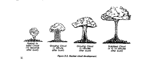
The development of nuclear clouds is divided into three stages: fireball, burst cloud, and stabilized cloud.
The fireball stage exists from the instant of the explosion until the generally spherical cloud of explosion products ceases to radiate a brilliant light. During this stage, do not look at the fireball. The brilliant light can cause permanent damage to your eyes.
As the brilliant light fades to a dull reddish glow, the fireball stage transforms into the nuclear burst cloud stage. At this point the cloud can be safely observed. The cloud may be either a spherical cloud (high airburst) or a mushroom-type cloud, with or without a stem (low air or surface burst). Relatively low-yield nuclear surface bursts have clouds similar to those produced by surface bursts of conventional explosives. Severe turbulence and rapid growth in cloud height and width are characteristic of this stage.
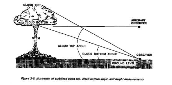
When the cloud ceases to grow in height, the stabilized cloud stage begins. Height stabilization occurs from about 4 to 14 minutes after the explosion, depending upon the yield. Nuclear burst angular cloud width (line item Lima, as explained in Chapter 2, for an NBC 1 report), and stabilized cloud-top/bottom angle or height (line item Mike) are measured during this stage. Figure 3-2 illustrates the growth of a nuclear cloud. After height stabilization (4 to 14 minutes) the cloud continues to grow. This is due to wind, not nuclear energy. For this reason, cloud measurements are not taken after H + 10 minutes.
Measurements of the nuclear burst cloud are taken at H + 5 minutes (line item Lima) or at H + 10 minutes (line item Mike).
Nuclear cloud measurements (parameters) have been correlated with yield. The results are in nomograms and on the ABC-M4A1 nuclear yield calculator. Use of the nomograms and the ABC-M4A1 is described later in this chapter.
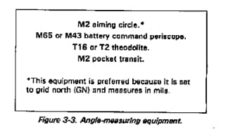
Specifically appointed and trained individuals determine input data at unit level. They are the operators of the angle-measuring equipment listed in Figure 3-3.
Unit SOPs detail the duties and circumstances concerning when and how measurements are taken. For accuracy, the following list of measurements (in order of reliability) is provided to aid in SOP development:
- Nuclear burst angular cloud width at H + 5 minutes.
- Stabilized cloud-top or cloud-bottom height measured at H + 10 minutes.
- Stabilized cloud-top or cloud-bottom angle measured at H + 10 minutes.
Angular Cloud Width
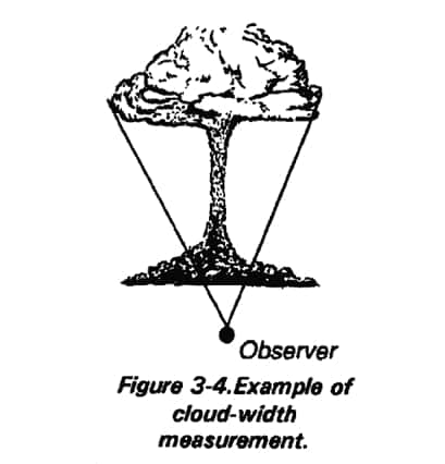
The width of the nuclear cloud is the angular dimension, in mils or degrees, of the cloud diameter. The optical equipment operator takes this measurement at H + 5 minutes. This measurement is made for nuclear clouds resulting from both air and surface bursts (see Figure 3-4). All units have some ability to take this measurement. The lensatic compass should be used if the listed equipment is not available. Use of binoculars for width measurement is extremely inaccurate.
The angular width of the cloud is measured five minutes after the detonation. The equipment operator (of equipment listed in Figure 3-3) measures the azimuth by sighting an azimuth to the left side of the cloud and one to the right side of the cloud. The difference between the numerical values of these azimuths is the angular cloud width. This measurement is reported (in degrees or mils) on line item Lima. Measurement is usually sent in mils.
Stabilized Cloud-Bottom or Cloud-Top Angle
The cloud-bottom angle measurement is the vertical angle (in mils or degrees) measured from GZ level (on ground level, if GZ level is not discernible) to the point of intersection of the stabilized cloud and the stem. Measurement is made at H + 10 minutes (see Figure 3-5). Cloud-bottom or cloud-top angle measurements are not taken for airbursts.
The cloud-top angle measurement is a vertical angle (in mils or degrees) measured from GZ level (or ground level) to the top of the stabilized cloud. This measurement is made at H + 10 minutes (see Figure 3-5).
These measurements are less reliable than measurements made at H + 5 minutes. Most units in the field cannot take cloud-bottom or cloud-top angle measurements. Therefore, they are not normally designated as observer units. These measurements cannot be made with a lensatic compass.
If the angular width of the cloud cannot be measured, the designated observer unit measures the cloud-bottom or cloud-top angle. Nondesignated observer units with angle-measuring equipment can also take this measurement. This measurement is made at H + 10 minutes. It is the vertical angle in mils or degrees from ground level to the top or bottom of a stabilized nuclear cloud. This data is entered as line item Mike.
The individuals specifically tasked to take cloud measurements report this data and other data specified in the unit SOP to the unit NBC defense team. If the unit is a designated observer, the defense team will format the data into an NBC 1 report. The report is transmitted per instructions in FSOP/OPLAN/OPORD or other written directions.
Cloud-Top or Cloud-Bottom Height
Helicopters and most small fixed-wing aircraft have a limited capability to determine cloud height. Surface ceiling and enemy ADA threat are the principal reasons for this limited capability. This measurement can be made with high-performance USAF, USN, and USMC aircraft. NBCC must coordinate with other service liaison officers to make arrangements to measure cloud height.
Cloud height can be measured with radars. Again, NBCC coordination is required to establish this data source. Radar may also be helpful in resolving actual number of bursts, GZs, and yields.
Observer Position
Use UTM coordinates or use a place name. Enter this location on line item Bravo of the NBC 1 nuclear report. Line item Bravo is required on all reports from ground observers and should be encoded. This is the location of the angle measuring equipment. It may or may not be the unit’s location.
Another important factor in determining the extent and effect of nuclear detonations is the location of ground zero (GZ). This is reported as line Foxtrot on the NBC 1 report.
Location of Ground Zero/Azimuth to the Attack
If the GZ cannot be observed, measure the azimuth from observer to the center of the stem (surface burst) or nuclear burst cloud (air burst). Enter this data as line item Charlie of the NBC 1 nuclear report. If the GZ can be observed, determine the UTM coordinates or place name. Enter this data as line item Foxtrot (actual). Omit line item Charlie. (Aerial observers may provide estimated or actual GZ, depending on altitude, orientation, terrain, and visibility conditions). GZ must be observed to use line item Foxtrot (actual).
Unit Level Procedures
Unit level is defined as any level that does not have an organic NBCC. Unit level procedures for locating GZ and estimating yield are much leas complicated. The emphasis is placed on speed of the calculation, rather than on accuracy. The NBC 2 report depends heavily on radio nets. The integrated battlefield will pose serious communications problems to these nets.
Changing frequencies and call signs several times a day causes other problems. All these problems, coupled with an aggressive enemy electronic warfare program, will delay message traffic between higher and lower headquarters. Therefore, at the unit level, an independent means of calculation must be used until the NBC 2 report data reaches this level.
Any unit that is not part of the designated observer system is obligated to take cloud measurements to the best of its ability and record all observed burst data. These data are recorded in the NBC 1 nuclear report format. They are not reported to higher headquarters unless specifically requested. All units use this data to locate GZ and to estimate yield.
Location of Ground Zero
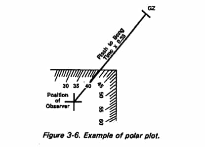
At unit level, GZ is located in either of two ways. For small yield weapons, direct observation may provide actual GZ location. Units do not, however, reconnoiter for the GZ location. The other method used at unit level is called the polar plot (see Figure 3-6).
Unit commanders are interested in obtaining a gross fix on the GZ location. This enables rapid evaluation of the burst to estimate the situation. Polar plot techniques are based on flash-to-bang time and the speed of sound (350 meters per second or 0.35 kilometers per second). The NBC defense team makes an approximation of the distance between GZ and the observer, in kilometers. They multiply the flash-to-bang time (data on line item Juliet of the NBC 1 report) by 0.35 kilometers per second.
Distance between GZ and observer = flash-to-bang time (sec) x 0.35 km/sec
Once this distance has been established, perform the following four steps:
Step 1. On the situation map, plot the observer location. This is line item Bravo on the NBC 1 nuclear report.
Step 2. Using a protractor, mark the azimuth from the observer position to the attack location. Convert magnetic azimuth to grid azimuth. This information is found on line item Charlie of the NBC 1 report.
Step 3. Draw this azimuth to the length previously calculated as the distance between GZ and the observer.
Step 4. Read the grid coordinates of the place where the azimuth line in Step 3 ends. This is an approximate plot of the GZ location.
Yield Estimation
On Shore
Only higher headquarters will have classified intelligence data that can be used as a comparison tool for resolved yield. Also, unit-level work conditions will be so varied that the use of nomograms will be difficult in most cases. Few, if any, units will have sufficient personnel to dedicate to an NBCC-type mission. Commanders at these levels need only an approximate yield value for entry into the broad yield groups of the effective downwind message.
This message is used for the simplified fallout prediction, discussed in detail later in this chapter. In any case, the apparent accuracy of the yield estimation nomograms is unnecessary.
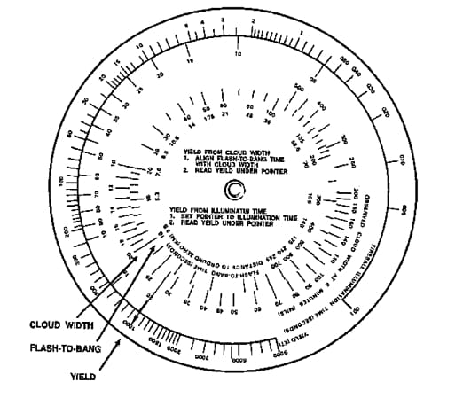
The M4A1 nuclear yield calculator (Figure 3-7) is designed to provide rapid yield estimation based on any parameter except cloud-top or cloud-bottom height. This calculator is a part of the M28A1 RADIAC calculator set, NSN 6665-01-130-3616. Instructions for use of the M4A1 calculator are on the instruction card in the set. This card also provides check problems. Upon receipt of the M4A1 calculator, the user should solve the example problem on the instruction card. If the calculator will not solve the example problem to within the specified tolerance, it must be destroyed and a new one obtained. Complete operating instructions for the M4A1 are in TM 3-6665-303-10.
There is one problem with the M4A1 calculator of which the unit NBC defense team must be aware. The calculator is a round nomogram with a fixed hairline. Because of this, there are situations in which the yield pointer may go off scale on the high or low ends of the yield scale. Additional burst information should clarify unexpected yield estimates not consistent with the use of tactical nuclear weapons. Familiarity with the calculator and an understanding of the size of a nuclear cloud in relation to the observer-GZ distance (flash-to-bang time) will eliminate these problems.
For example, a nuclear cloud is 20 mils wide. Flash-to-bang time was 10 seconds. This is a small cloud that is very close to the observer, indicating a small yield. The calculator shows a yield of 1,000 kilotons, but the actual yield is less than 0.02 kiloton. Conversely, a nuclear cloud-top angle of 80 degrees with a flash-to-bang time of 120 seconds is a large cloud very far away. This time the calculator shows a yield of 0.02 kiloton, but the actual yield is greater than 10,000 kilotons.
The M4A1 calculator is a rapid yield-estimation method designated specifically for unit level use. Its durability, size, and ease of operation make it the most suitable method. All members of the unit NBC defense team are trained in its use. Nomograms are not used at unit level because of adverse conditions.
The GZ location and estimated yield calculated at unit level are used to create a simplified fallout prediction. Upon receipt of the NBC 2 report from the NBCC, the original simplified fallout prediction is revised, using the new data. When the NBC3 report is received, it supersedes the revised simplified fallout prediction. This approach allows the unit commander to make estimates and decisions based upon the best available information at that time.
Onboard Ships
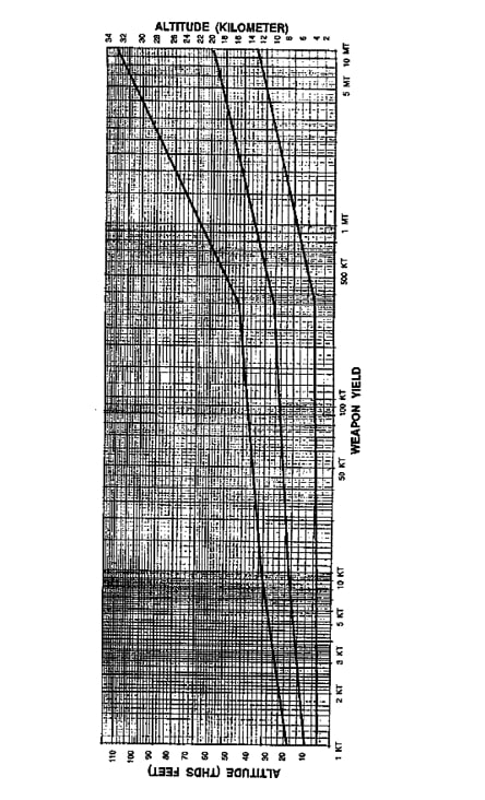
If stabilized cloud-top height or cloud-bottom height can be measured, then Figure 3-8 may be used to estimate the yield. Line up hairline with information given on line Mike, (convert from meters or feet to kilometers or thousands of feet.) Pin down where hairline crosses line in graph. Then plot so hairline is parallel. Read weapon yield on bottom of graph. When cloud-top or cloud-bottom parameters are not available, ships will have to use the methods described in the preceding paragraphs for ground forces.
Significance of Fallout Ashore Versus at Sea
The detailed and simplified procedures for fallout prediction are intended for use by all three services. The predictions are based on assumed land surface bursts. It is recognized that the fallout from a sea surface burst may be different, but very little direct information is available on fallout from bursts on the surface of deep ocean water.
It also must be stressed that the sea acts as an absorbent of and shields against radioactive products. But, these products may remain a hazard on land until they have decayed.
Another important difference is that recipients of warnings ashore do not have the mobility of ships at sea, and in most cases must deal with the hazard. Therefore, ships will be particularly interested in the determination of the approximate area where fallout will reach the surface at a given time after burst.
Ships with a meteorological capability maybe able to obtain the required meteorological data for computation of effective downwind, using standard pressure level winds. Basic wind data for this purpose are generally available also from meteorological sources (airbases, meteorological ships, or mobile weather stations).
Ships which do not have a meteorological capability will normally predict fallout areas by using the simplified procedure. Fallout prediction and plotting of fallout areas on board naval ships is discussed in this chapter.
Flash-to-Bang Time
At the instant of the blue-white flash, cover eyes, hit the ground, and start counting slowly–1,000 and 1, 1,000 and 2, 1,000 and 3, and so on–until the arrival of the shock wave or bang. Make a mental note of the count on which the shock wave arrives (for example, 1,000 and 4). If the observer has a watch and can note the exact time (in seconds), the watch can be used to record the flash-to-bang time. This data is entered as line item Juliet on the NBC 1 nuclear report. Remain where you are until debris has stopped falling. It must be noted that there will be two shock waves–one blowing in one direction, and the other blowing a few minutes later in the opposite direction. If the bang is-not heard in five minutes (a count of 1,000 and 300), continue with other measurements.
Type of Burst and Time of Attack
After the second shock wave has passed, uncover your eyes, and read the watch to the nearest minute. This data is entered as line item Delta of the NBC 1 nuclear report. Observe the developing cloud to see if the burst was an airburst by noting the shape and color of the cloud or the absence of a stem. If the cloud is lighter in color than the stem, or if the stem is ragged or broken (does not solidly connect with the cloud), record “air” as line item Hotel of the NBC 1 nuclear report. If the stem is thick and dark, and it connects with the cloud, record “surface” as line item Hotel. When the cloud does not match any mental image for air or surface, record “unknown” as line item Hotel.
“Unknown” also may be recorded whenever the attack occurs at night. A subsurface burst is recorded as “surface,” only if the detonation ruptures the surface. This of data also is recorded on line item Hotel.
Recording and Reporting Nuclear Burst Data
Each unit, designated and nondesignated, uses the data to locate GZ and estimate the yield. Polar plot techniques are used to locate GZ. Yield is estimated with the M4A1 yield calculator. GZ and yield are used with the effective downwind message to make a simplified fallout prediction. Effective downwind messages and simplified fallout predictions will be explained later in this chapter. This prediction is used until the NBC 2 report is received. Then the simplified fallout prediction is revised and reevaluated. The NBC 3 report will follow later. The NBC 3 report is more accurate and supersedes all simplified predictions.
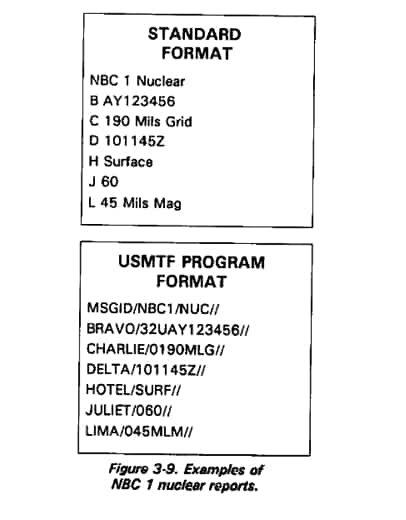
Examples of nuclear burst reports are shown in Figure 3-9. These reports follow the standard NBC 1 nuclear report format. These examples in no way limit the variety of reports. Further, unit NBC defense teams are not confined solely to the use of the line items in these examples. Other line items may be added at the user’s discretion.
Evaluating Data
Data evaluation consists of locating GZ, estimating the yield of the weapon, confirming the date-time group of the burst, and assigning a strike serial number. It is performed at the NBCC. If the unit level establishes a serial number, it will only be for that unit’s use and never transmitted higher.
All calculations of GZ locations and yields developed at unit level are estimates. These calculations are based on data gathered by one unit. Methods of calculation are simple and abbreviated. These reports also contain other data. Unit-level estimations are never transmitted to higher headquarters.
The NBCC is responsible for the NBC 2 report. This report reflects the GZ location, yield, and other data that the entire command will use for fallout predictions. This ensures that all units will make the same fallout prediction.
NBCC Procedures
NBCC techniques compare the data from many sources. Much of this data is not available to any one unit. Only the NBCC is authorized to assign strike serial numbers. This is generally from a block of numbers assigned to the division by corps. This block of serial numbers is usually listed in FSOP/OPLAN/OPORDs. The serial numbers usually identify the corps, division and/or brigade areas, and the number of the strike.
Date and Time of Attack
The date and time of the attack are always reported. The time zone used is specified by FSOP/OPLAN/OPORD or is contained in other instructions. The NBCC conducts time checks with designated observers and converts all times to Zulu time.
Ground Zero Location
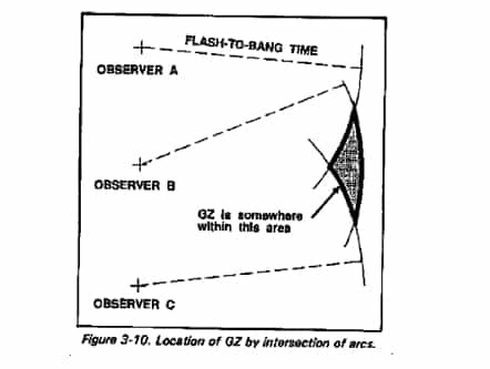
At the NBCC, GZ location is always located before the yield is estimated. The NBCC uses several methods and data sources to locate GZ. Some of these methods are plots of intersecting azimuths, radar reports, and aviator reports. If line item Foxtrot (actual) data on the NBC 1 report is not available, other methods are used to confirm this data. When azimuth data are incomplete, arcs for radii of flash-to-bang distances from two or more observers can be used. The NBCC can request NBC 1 reports from nondesignated units to supplement data from designated units.
Combinations of azimuths and radii of flash-to-bang distances also can be used. This is done by multiplying flash-to-bang time submitted on NBC 1 reports by the speed of sound (0.35 kilometers per second) to determine a distance. Once the observer location has been plotted, the flash-to-bang time distance can be drawn as an arc. If several arcs can be drawn, a gross fix of GZ can be determined. This is the most accurate method to estimate the location of GZ. See Figure 3-10.
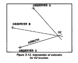
The principal GZ location method is a plot of intersecting azimuths sent by designated observers. (This information is found on line item Charlie of the NBC 1 reports.) To locate GZ using a plot of intersecting azimuths, follow these four steps:
Step 1. On the operations map overlay, locate and mark the position of each observer unit, using data at line item Bravo. Line item Bravo must be encoded if using an unsecure radio net. Therefore, these observer locations may have to be decoded prior to actual plotting.
Step 2. Determine each azimuth to be plotted. (This information is at line item Charlie.) Convert all magnetic azimuths to grid azimuths. Using a protractor, mark each azimuth from each observer position. Draw each azimuth to the distance necessary for them to intersect.
Step 3. Post any data that assists in the determination of GZ location (such as, radar reports and pilot reports).
Step 4. Evaluate the data. The result of intersecting azimuths is an estimation of GZ location. GZ location is reported on the NBC 2 report at line item Foxtrot, qualified with the word “estimated,” unless Foxtrot (actual) information is used in the determination. Line item Foxtrot must be encoded if using an unsecure radio net.
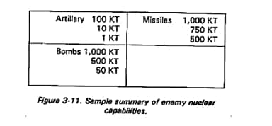
In using this summary, the NBCC compares the estimated yield with known enemy yields. The estimated yield and other intelligence sources, such as delivery means, depth of the attack from the front line of troops, type of burst, and other circumstances concerning the attack, will indicate which known enemy yield was actually used. Only this resolved yield is reported to field units. A simplified summary of enemy nuclear capabilities is shown in Figure 3-11.
Disregard azimuths that do not intersect with other azimuths. Whenever azimuths do not cross to form a clear GZ location, the center of the plot is taken as GZ location. The NBCC will request exact GZ coordinates from aviation assets when aviation missions permit. Figure 3-12 shows an intersection of azimuths for GZ location.
Another GZ location technique involves the use of line item Papa Alfa. Some air defense artillery radars have the ability to paint an outline of the nuclear cloud on radar scopes. The radar operator can determine coordinates of H + 5 minutes after burst, which outline the stabilized nuclear cloud as if it were viewed from the top. These coordinates may be sent as UTM coordinates. Coordination between the NBCC and the unit that sends radar data is required. This coordination must establish precedence of the report and communication channels to be used.
Upon receipt of the data at the NBCC, the coordinates are plotted on the map, and the cloud contour is drawn. The center of the outline is the GZ location. If the measurements are taken at H + 5 minutes after burst, there is a high assurance that GZ has been accurately fixed. This GZ location technique is most valuable at night or when observer data cannot fix GZ location with 90 percent or greater assurance.
Yield Estimation
Before the yield can be estimated, you must know the location of GZ and the position of the observer when the cloud measurements were taken. Rather than require field personnel to solve complex formulas, the nuclear burst parameters are presented in nomograms. Each is an independent means of estimating yield. Emphasis is on estimating the yield. All nomograms are designed to provide approximate yields.
Flash-to-bang time (line item Juliet) is not used at NBCC level for yield estimation, except as a last resort. This information is usually regarded as unreliable because of the stress associated with slow counting immediately after an attack. Instead, the NBCC uses the distance (in kilometers) between GZ and the observer. Plotting this data (intersecting azimuths) represents the best method of determining the distance between GZ and observer location. Flash-to-bang time is used for yield estimation only when azimuth information is not reported or is incomplete.
Nuclear Burst Angular Cloud Width
NBCC members use the nomograms in Appendix E (Figure E-5) to determine yield, based on the nuclear burst angular cloud width, and distance between GZ and the observer. The right-hand scale is the nuclear burst angular cloud width in mils and degrees. The center scale is the distance in kilometers between GZ and the observer. The left-hand scale is the yield in kilotons (KT).
To use this nomogram, place a hairline from the point on the right-hand scale (representing the nuclear burst angular cloud width at H + 5 minutes) through the point on the center scale (representing the distance between GZ and the observer). Read the yield where the hairline crosses the yield scale.
For example, a plot of designated observer positions and reported azimuths has been made. Observer A reported a nuclear burst angular cloud width on line item Lima of 280 mils. The distance between observer A and GZ is 21 kilometers. To estimate the corresponding yield by using the nomogram, use a hairline to connect 280 mils on the right-hand scale with 21 kilometers on the center scale. The point of intersection of the hairline and the left-hand scale, is a yield of about 50 kilotons.
Stabilized Cloud-Top or Cloud-Bottom Height
Cloud-top or cloud-bottom height, when stabilized, can be closely measured by pilots in jet aircraft. The NBCC must coordinate with liaison officers to have airmail in the area determine this height. Height can also be measured by some ADA radars. Measurements, in meters or feet above the earth’s surface, must be made at H + 10 minutes. Data are reported on line item Mike.
NBCC members use the nomograms in Appendix E (Figure E-3) to correlate these measurements with yield. Distance between GZ and observer is not required.
The extreme left and right scales on the nomogram are yield in kilotons (KT) and megatons (MT). The scale second from the left is the cloud-top height at H + 10 minutes in thousands (103) of meters or feet. The scale third from the left is the cloud-bottom height, also at H + 10 minutes. It, too, is graduated in thousands of meters or feet. The other scales on the nomogram (two-thirds stem height, cloud radius, and time of fall) are not used in yield estimation. These scales are used in detailed fallout prediction.
To use the nomogram, determine stabilized cloud-top or cloud-bottom height from line item Mike of NBC 1 reports or as reported by pilots through liaison officers. Place a hairline directly over the reported data and pin the hairline to the nomogram. Pivot the hairline until it crosses the outside yield scales at the same value. This value is the estimated yield.
For example, a cloud-bottom height of 21,000 feet has been reported. To estimate the corresponding yield, place a hairline on the mark representing 21,000 feet (21) on the third scale from the left. Pin the hairline and pivot it about this axis until equal values are read on the extreme left and right yield scales. Read a yield of 10 kilotons.
Stabilized Cloud-Top or Cloud-Bottom Angle
The NBCC uses the nomogram in Figure E-4 in Appendix E to find yield, given the distance between GZ and the observer, and either the stabilized cloud-top angle or the cloud-bottom angle. The right-hand scale gives the distance in kilometers from GZ to the observer and the fIash-to-bang time in seconds counted by the observer. The center scale is the cloud-top or cloud-bottom angle in mils or degrees. The left-hand scale is actually two scales. The left side of this scale lists the yields to be read when using the cloud-bottom angle; the right side of this scale lists the yields to be read when using the cloud-top angle.
To use this nomogram, place a hairline through the point on the right-hand scale representing distance between GZ and the observer and through the point on the center scale representing either the cloud-top or cloud-bottom angle. At the point of intersection of the hairline and the left-hand scale, read the yield. If cloud-top angle was used on the center scale, read yield on the right side of the left-hand scale titled yield-cloud top (km). If a cloud-bottom angle is used, read the yield on the left side of the left-hand scale titled yield-loud bottom (KT).
For example, a designated observer reports an angle to cloud bottom (line item Mike) of 200 mils. Distance between GZ and this observer is 42 kilometers. Place a hairline from 42 kilometers on the right-hand scale through 200 mils on the left side of the middle scale. Read the yield as 55 kilotons on the left side (cloud bottom) of the left-hand scale. This yield calculation is only a field estimate.
If an observer reports cloud-top and cloud-bottom angles, use both in the yield estimate. Each angle will result in a different yield. Use the average of the two yields.
Yield Estimation From Radar Data
When nuclear attacks occur at night, measurements of cloud parameters may be impossible. Under these conditions a good yield estimate can be made by the NBCC if data from radars are available at line item Papa Alfa of the NBC 1 nuclear report. A plot of this data will outline the nuclear cloud at its point of maximum lateral growth. To estimate yield, the NBCC measures the radius of the outline of the cloud and consults Table 3IV-1 in Chapter 3 of FM 101-31-2 (S). This data is classified and beyond the scope of this manual. Yield can be confirmed by entering the nomogram in Figure E-3 with cloud radius, and check the yield, or vice versa.
Illumination Time
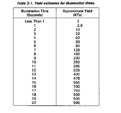
During the hours of darkness or poor visibility, yield may be estimated from the measurement of illumination time. Use this method only when it is impossible to obtain cloud parameters as previously discussed. This yield estimation method only gives an estimate on the order of a factor-of-ten. In other words, a yield estimate of 20 KT could be as low as 2 KT or as high as 200 KT.
Under no circumstances should the observer look directly at the fireball. This will cause permanent damage to the eyes. Observers can sense, with eyes closed, when the intense light has faded. An observer in a foxhole can look at the floor of the foxhole. Counting procedure is the same as that for flash-to-bang time. The person counting illumination time stops counting when the light begins to fade. The individuals specifically tasked by unit SOP to count illumination time must be trained to do so. Quick reflex action and presence of mind are required. Table 3-1 shows rough estimates of yield, using illumination time.
Resolved Yield
Each of the yield estimation techniques is presented in order of decreasing reliability, with results in approximate yields. There also will be occasions when the data from several observers, concerning a single attack, will not result in the same yield. Estimates for each strike are averaged. The yield determined from nomograms is the mid-point of the process. Again, this is an approximate yield.
The actual yield reported to the field units is called the resolved yield. To determine the resolved yield, the NBCC maintains a summary of enemy nuclear capabilities. This summary may reflect order-of-battle, delivery units, and known yields. This data is determined from G2 and other intelligence sources. FM 101-31-2(S) also offers data on enemy yields and delivery systems.
If the resolved yield is less than the estimated yield and the estimated yield lies in a higher yield group on the effective downwind message, use this higher yield when reporting yields to field units. The higher yield will be used until data can be refined and monitoring reports are received.
NBC 2 Nuclear Report
The NBC 2 report reflects the evaluated nuclear burst data. Raw data is automatically submitted by designated observer units each time the enemy attacks with nuclear weapons. It represents the detailed evaluation of all raw data.
The NBC 2 report has a precedence established in FSOP/OPLAN/OPORD or other written instructions. Precedence is based upon urgency. An NBC 2 report may have a different precedence for a unit in a danger zone compared to a unit not in an affected area.
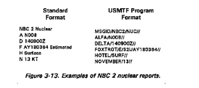
NBC 2 reports are created for all bursts–air, surface, and unknown. When surface or unknown are reported as the type of burst, fallout predictions are made. Users of NBC 2 reports are not limited to the use of the line items shown in the example. Other line items, as appropriate, may be added. Figure 3-13 shows examples of NBC 2 reports.
Communication means for the NBC 2 report is established by FSOP/OPLAN/OPORD or other written instructions. Each NBC 2 report is sent to all affected subordinate units and higher and adjacent headquarters. This allows planning for future missions or boundary changes.
Subsequent data may be received after the NBC 2 report is sent. If this data changes the yield or GZ location, the newer data is sent in a new NBC 2 report. The same strike serial number and date-time of attack are used.
Once the NBCC staff determines the resolved yield, they formulate an NBC 2 report. In theory this is done only at division NBCC level. However, in practice the NBC 2 report may be done at battalion or brigade level. In some special cases, the NBC 2 report may be generated at unit level. Any command level that has access to two or more NBC 1 reports, upon which an accurate yield and exact location for ground zero may be determined, may produce an NBC 2 report. However, if NBC 2 reports are provided by higher headquarters, they must be used; because, generally, higher headquarters will have more accurate data.
Strike Serial Number
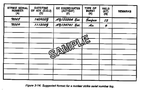
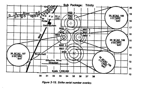
The NBCC serves as a focal point for all requests for information concerning nuclear strikes. It is responsible for assigning a strike serial number to each nuclear attack, friendly or enemy, that occurs within its assigned area. A record of these numbers is kept in a log or on a map overlay. A suggested format for a log is shown at Figure 3-14 and a map overlay at Figure 3-15.
Note: The resolved yield is based on the information provided by the G2 on enemy nuclear capabilities by weapon type.
Any system of numbering nuclear strikes designated by SOP is permitted. The system maybe all numbers, all letters, or alphanumerical. Integration of the NBCC headquarters designation in the serial number is also permitted. The headquarters responsible for the area of operation should not assign blocks of strike serial numbers to subordinate units.
Once the unit receives the NBC 2 nuclear report, the unit NBC defense team takes the report and a current effective downwind message, and prepares a simplified fallout prediction. Effective downwind messages will be explained later in this chapter.
Simplified Fallout Prediction
The simplified fallout prediction system provides small unit commanders an immediate estimate of the fallout hazard. The commander uses the simplified fallout prediction in the decision-making process. A current effective downwind message, nuclear burst information (NBC 2 nuclear report), and a simplified fallout predictor (M5A2 or field expedient) are required to prepare a simplified fallout prediction. It is superceded upon receipt of an upgraded NBC 2 nuclear report only if there is a disparity between the initial NBC 2 report and the upgraded NBC 2 report. Otherwise, it is superceded by an NBC 3 nuclear report from higher headquarters.
To use the simplified fallout prediction system, a unit should–
Train on the simplified fallout prediction system.
Establish communications with the battalion to maintain current wind data.
Have the necessary forms and overlays ready for use. These include NBC 2 nuclear report formats, effective downwind message formats, and the M5A2 fallout predictor. If the M5A2 fallout predictor is not available, a field-constructed predictor and the nomogram in Figure E-6 in Appendix E may be used.
Wind Data
To use the simplified fallout prediction, you need the effective wind speed and downwind direction. This information is prepared by the NBCC as an effective downwind message, and it is transmitted to subordinate and adjacent units each time new upper air wind data are received. Effective downwind messages should be received from the division NBCC every 12 hours. However, if one is not received within 12 hours, the latest message should always be used. Effective downwind messages more than 12 hours old, however, should not be used for fallout prediction.
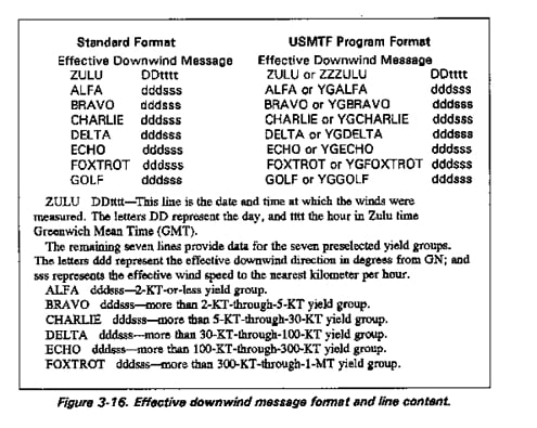
The format for the effective downwind message is a series of eight lines preceded by the phrase “Effective Downwind Message.” The significance of each line item is indicated inFigure 3-16.
For example, an effective downwind message reads Delta 090025. The individual using this information knows that when the Delta line is used, the yield of the weapon is more than 30 KT but no more than 100 KT. Use of the Delta line indicates that the fallout prediction was determined from a downwind direction of 90 degrees and an effective wind speed of 25 kilometers per hour.
Effective Downwind Message
Preparing an EDM is similar to preparing a detailed fallout prediction, which will be explained later in this chapter. The difference is the EDM is prepared for specific yields and it is used by a unit to prepare a simplified fallout prediction. The NBCC is responsible for preparing and disseminating the EDM. This normally is done once every twelve hours.
Preparation of a Message (Wind Data)
Step 1. Obtain the cloud-top height, cloud-bottom height, and two-thirds stem height (from Figure E-3) for each of the following yields: 2 KT, 5 KT, 30 KT, 100 KT, 300 KT, 1 MT, and 3 MT. This information is also on DA Form 1971-3-R (Effective Downwind Message Worksheet). A blank DA Form 1971-3-R can be found in Appendix H.
Step 2. Place a sheet of overlay paper over the wind vector plot, and mark a GN reference line and GZ. Preparation of wind vector plots is outlined in Appendix D. Mark the cloud-top height, cloud-bottom height, and two-thirds stem height for the 2-KT yield (use the values obtained in step 1). Draw radial lines from GZ through these three points.
Note: It is important to understand that all military significant fallout is contained between 2/3 stem and cloud top height. In relation to this fact all of the wind vectors from where 2/3 stem is plotted up to cloud top height must fall between these two radial lines. If not the closest radial line must be moved to include these vectors. Some times it may be necessary to move only one, or both 2/3 stem and cloud top height, a radial line that has been moved will have the same nomenclature as the original line.
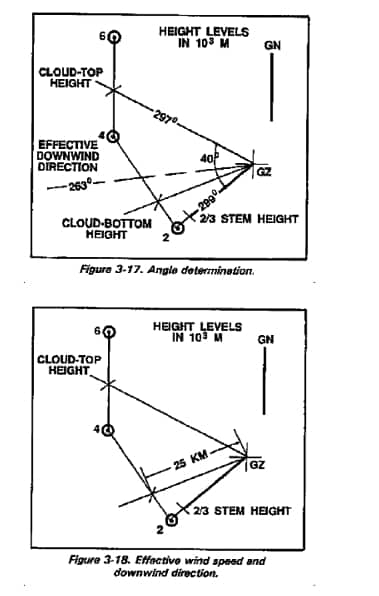
Step 3. To determine the effective wind speed, measure the distance along the cloud-bottom radial line from GZ to its intersection with the wind vector plot at the cloud-bottom height point. Divide this distance by the time of fall from the cloud bottom (Figure 3-17), or multiply by the reciprocal as shown on the EDM worksheet.
Note: A situation may arise when the effective wind speed for one or more yield groups is less than 8 kmph. In this case the downwind distance for Zone I is determined, using the nomogram in Figure E-6’s (Appendix E) zone of immediate concern. Enter the nomogram with the effective wind speed of 8 kmph on the left-hand scale, and the highest yield for each yield group on the right-hand scale. Then, read the downwind distance for Zone I on the center scale.
Step 4. To determine the effective downwind direction, use a protractor to bisect the angle formed by the cloud-top height radial line and the two-thirds stem height radial line. Measure the azimuth of the bisector in degrees from GN. This is the effective downwind direction (Figure 3-18).
Step 5. Measure the angle between the cloud-top and two-thirds stem. In some cases the angle will be more than 40 degrees. In those cases if the angle is an odd number, round the angle to the next highest even number, and record it on the worksheet in the expanded angle column for the appropriate yield group.
Step 6. Repeat steps 2 through 5 for the remaining yield groups. Use a separate sheet of overlay paper for each yield group,
Step 7. Complete the EDM portion of the work sheet, based on the data and calculations.
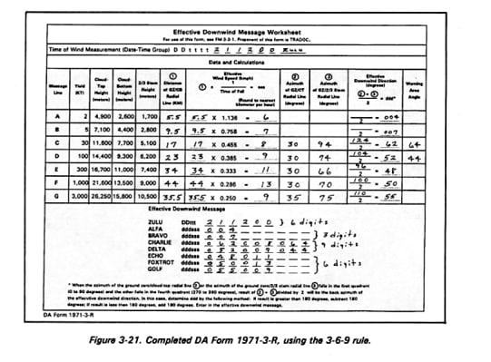
Remember the 3-6-9-digit rule:
3 digits mean winds less than 8 kmph, and digits represent Zone I distance.
6 digits mean normal message.
9 digits mean expanded radial lines to a given number of degrees.
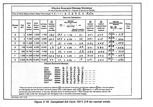
An example of a completed worksheet and an effective downwind message for normal winds is depicted in Figure 3-19.
A worksheet with the two types of special cases discussed is depicted in Figure 3-21.
Special Cases
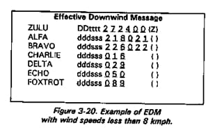
When the effective wind speed is less than 8 kmph for a given yield group, the applicable line will contain only three digits (Figure 3-20). These three digits will represent the radial line distance (obtained by entering the nomogram in Figure E-6 with the estimated yield and 8 kmph) of Zone I. In this case no wind speed is given, and the fallout pattern will be two concentric circles.
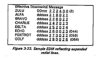
Another special case occurs when the fallout is not expected to fall within the normal 40-degree angle of the prediction. In this case the appropriate line on the effective downwind message has nine digits. The first six digits represent wind direction and wind speed. The last three digits show the angle in degrees between the left and right radial lines (seeFigure 3-22).
Naval Effective Downwind Message
Effective downwind speed and downwind direction (the direction towards which the wind is blowing) vary with the yield. Seven downwind speeds and downwind directions are transmitted in the Naval effective downwind message, corresponding to seven preselected yield groups. These groups are–
ALFA 2 KT and less
BRAVO more than 2 KT to 5 KT
CHARLIE more than 5 KT to 30 KT
DELTA more than 30 KT to 100 KT
ECHO more than 100 KT to 300 KT
FOXTROT more than 300 KT to 1 MT
GOLF more than 1 MT to 3 MT.
NAV EDMs can be produced at Naval NBC centers from actual wind data, or at designated meteorological centers from computer-originated forecast wind data.
A fallout prediction is prepared for the largest yield within each of the seven standard weapon yield groups–2 KT, 5 KT, 30 KT, etc. And, the calculated downwind directions and effective downwind speeds are transmitted to naval forces and ships in the NAV EDM.
The data will be transmitted in the following basic format:
NAV Effective Downwind Massage
ZULU
DDttttZ
ALFA
dddFFF
BRAVO
dddFFF
CHARLIE
dddFFF
DELTA
dddFFF
ECHO
dddFFF
FOXTROT
dddFFF
GOLF
dddFFF.
In the NAV EDM, ZULU DDttttZ is the date (DD) and time (ttttZ) in GMT, at which the actual wind conditions were measured (for example, 250600Z is the 25th day of the month at 0600 GMT).
The ddd digits reflect effective downwind direction in degrees, and FFF effective downwind speed in knots (ALFA 080025 is a downwind direction of 080 degrees and 025 an effective downwind speed of 25 knots) valid for yields of 2 KT or less.
Normally, a NAV EDM will be valid for six hours from the time the winds were measured (item ZULU in the NAV EDM). Should the wind conditions change significantly within the six hours, a new NAV EDM will be transmitted.
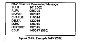
An example of a NAV EDM is shown in Figure 3-23.
Note: Naval ships receiving NBC reports from non-naval sources may have to convert metric units into maritime units of measurements.
Special cases exist with the NAV EDM. These cases occur when the effective wind speed is less than 5 knots and when the angle of the sector must be expanded.
When the effective downwind speed is less than 5 knots for a given yield group, the applicable line of the NAV EDM contains only three digits, giving the downwind distance of Zone I in nautical miles. An effective downwind direction is not transmitted in the NAV EDM, since in this case the downwind distance of Zone I describes the Zone I as a circle around GZ. Zone II will then be another circle around GZ, the radius of which is double the radius of the Zone I circle. Use 5 knots when estimating arrival time.
When, in the NAV EDM, a bracket containing a figure is added to the normal 6-digit figure, it means that the angle formed by the two radial lines must be expanded to form an angle of the number of degrees indicated in the bracket. In Figure 3-23, yield group GOLF, the increased angle is indicated to be 60 degrees–30 degrees to each side of the downwind axis. The angle expansion can also be given by adding a seventh digit to any of the yield groups.
Preparation of a Message (Constant Pressure Data)
The procedure for preparing the effective downwind message from a constant pressure surface wind vector plot is modified in three steps:
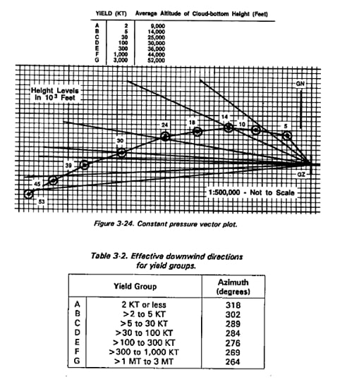
Step 1. On the wind vector plot (Figure 3-24), draw radial lines from GZ through the points on the wind vector plot representing the average cloud-bottom heights for the yields of interest. The average altitudes of cloud-bottom heights of the yields used in the simplified prediction method are also shown in Figure 3-24.
Step 2. Calculate the effective downwind directions and wind speeds:
a. Measure the azimuth of each radial line drawn which corresponds to the yield and altitude (Step 1). These azimuths (Table 3-2) are the effective downwind directions for each yield group in this example.
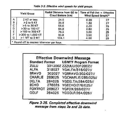
b. Measure the length in kilometers of each radial line, and divide these distances by the time of fall. The results are the effective wind speeds, as shown in Table 3-3.
Step 3. Prepare the EDM, using the data from steps 2a and 2b. Figure 3-25 shows the completed EDM.
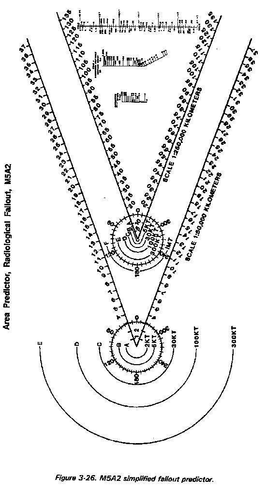
M5A2 Fallout Predictor
The M5A2 radiological fallout predictor (Figure 3-26) is a transparent device used to outline the zones of hazard resulting from surface bursts for preselected yield groups. The M5A2 fallout predictor is composed of two simplified predictors and a nomogram for determining the downwind distance of Zone I. One simplified predictor is drawn to a scale of 1: 50,000; the other predictor is drawn to a scale of 1: 250,000. Each predictor contains six preselected yield groups (A, B, C, D, E, and F).
Each simplified predictor consists of four major parts:
Part 1. An azimuth dial for orientation.
Part 2. Semicircles depicting stabilized nuclear cloud radii drawn about GZ and showing the area of contamination for each of the preselected yield groups.
Part 3. A map scale calibrated in kilometers along two radial lines extending out from the center of the azimuth dial.
Part 4. Nomogram for determining the downwind distance of Zone I.
The nomogram from Figure E-6, consisting of three scales, is positioned between the radial lines of the M5A2. It is used to determine the downwind distance of Zone I. The left-hand scale is the effective wind speed in kilometers per hour. The center scale is the downwind distance of Zone I in kilometers. The right-hand scale is the yield in kilotons.
To convert the M5A2 to conform with STANAG 2103, draw a 28-kilometer semicircle around GZ, and label it with the letter G. This line is used for bursts greater than 1 megaton, but less than or equal to 3 megatons.
Procedures for Using Simplified Method
Use of the M5A2 requires a current effective downwind message, an actual or estimated yield of the nuclear weapon detonated, and location of GZ. Normally, the user of the M5A2 will obtain the yield and the location of GZ from measured data or from the NBC 2 nuclear report. Follow these six steps to prepare the prediction (See Figure 3-26, for fallout predictor.):
Step 1. Identify the prediction. Record the location of GZ and the date-time of burst on the predictor.
Step 2. Effective wind speed and downwind direction. Get this data from the appropriate line of the effective downwind message.
Step 3. Downwind distances of the zones. Determine the downwind distance of Zone I from the nomogram (Figure E-6) on the M5A2. Do this by connecting the effective wind speed and the point on the scale representing the yield with the straight edge or hairline.
Note: Use the actual or estimated yield, not the yield group.
Read the downwind distance of Zone I, in kilometers, at the point of intersection of the straight edge. The downwind distance of Zone II is twice that of Zone I. Draw arcs between the two radial lines, using GZ as center, with radii equal to the two downwind distances determined.
Step 4. Draw left and right tangents from the cloud radius line for the yield group (from Step 3) to the points of intersection of the radial lines and Zone I arcs of the predictor. This area represents the primary hazard.
Step 5. Label Zones I and II. Darken the remainder of the prediction perimeter with a grease pencil to emphasize the area of hazard.
Step 6. Time-of-arrival arcs. Draw in these arcs, using the effective wind speed.
Draw as many dashed time-of-arrival arcs between the radial lines or tangent lines as will fall within the zones. Label each time-of-arrival arc as hours after H-hour (for example, H + 1, H + 2). Estimate times of arrival by using the effective wind speed (procedure indicated in the next paragraph). If a time-of-arrival arc coincides with a zone boundary, extend the zone boundary with a dashed line, and label with the appropriate time of arrival. Do not draw time-of-arrival arcs beyond Zone II.
Times of arrival can be estimated. Multiply the effective wind speed by the time of interest expressed in hours after the burst. Time-of-arrival arcs represent the expected downwind extent of fallout at specific times. These arcs are drawn as part of the fallout prediction. Estimate time of arrival of fallout at a specific distance from GZ by dividing the distance by the effective wind speed. The formula looks like this:
For operational purposes, the following rules of thumb may be applied to the actual arrival of fallout:
The actual arrival of fallout may occur as early as one-half of the estimated time of arrival. That is, if the estimated time of arrival of fallout is H + 4 hours, actual arrival of fallout may occur as early as H + 2 hours.
If actual arrival of fallout has not occurred at twice the estimated arrival time (or 12 hours, whichever is earlier), it may be assumed that the area will not receive fallout. For example, if the estimated time of arrival of fallout in an area is H + 5 hours and fallout has not occurred at H + 10 hours, assume that the area will not receive fallout. Also, if a unit expects fallout to arrive at H + 9, but it has not arrived by H + 12, assume it will not arrive at all.
Orientation. Make sure the scale of the M5A2 and the map scale are the same. Next, place the fallout predictor GZ point over the actual or assumed GZ on the map. Rotate the entire fallout predictor until the effective downwind direction in degrees on the azimuth dial is pointing toward GN.
The simplified fallout prediction is now complete, and the operational aspects of the fallout hazard can be evaluated.
Special Notes: Infrequently, the fallout wind vector plot prepared by the NBCC may have a warning area angle greater than 40 degrees. In these cases, state the greater angle on the effective downwind message for the yield group affected. Using units will expand the warning area beyond the fixed 40-degree angle of the simplified fallout predictor to correspond with the angle given on the effective downwind message. Angles must be expanded equally on both sides of the predictor. The expanded case example discussed later in this chapter shows how this is done.
Constructing a Simplified Predictor
If the fallout predictor shown in Figure 3-26 is not available, a predictor can be constructed from any pliable, transparent material to any desired map scale as follows:
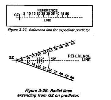
Step 1. Select an appropriate map scale. On a piece of pliable, transparent material or overlay paper, draw a thin dotted line (reference line) to a scaled length of 50 kilometers from a point selected to represent GZ (Figure 3-27).
Step 2. Draw and graduate in kilometers two radial lines from GZ at angles of 20 degrees to the left and to the right of the dotted reference line (Figure 3-28).
Step 3. On the side of GZ opposite the reference line, draw a series of concentric semicircles (using the selected map scale) having radii of 1.2 kilometers, 1.9 kilometers, 4,2 kilometers, 6.8 kilometers, 11.2 kilometers, 18.0 kilometers, and 28 kilometers). These figures correspond to stabilized cloud radii from nuclear bursts with yields of 2 kilotons, 5 kilotons, 30 kilotons, 100 kilotons, and 3 megatons, respectively.
Step 4. Label the semicircles. Starting with the semicircle closest to GZ and moving up from GZ, label the semicircles A, B, C, D, E, F, and G. Moving down from GZ, label the semicircles 2 kilotons, 5 kilotons, 30 kilotons, 100 kilotons, 300 kilotons, 1 megaton, and 3 megatons.
To use the field-constructed predictor, complete the prediction by determining the downwind distance of the Zone I from Figure E-6, Appendix E, using the procedures described earlier. Place the protractor over an actual or assumed GZ on the map and draw a line to represent the effective downwind direction for the desired yield group. Place GZ of the predictor over GZ on the map, and rotate the predictor until reference lines coincide with the effective downwind direction.
The simplified fallout prediction is verified only from the standpoint of using the correct yield and GZ location. This is done upon receipt of the NBC 2 nuclear report from higher headquarters. Identify the simplified fallout prediction by entering the strike serial number (line Alfa of NBC 2), coordinates of GZ, and date-time group of detonation on the predictor. The following examples illustrate simplified fallout predictions.
Simplified Fallout Prediction (Normal Case)
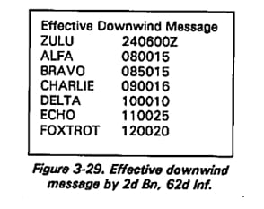
The S3, 2d Battalion, 62d Infantry, has the effective downwind message in Figure 3-29, based on the following situation scenario:
At about 240600Z a nuclear burst occurred at a point estimated to be MN553298. A measurement of the flash-to-bang time and nuclear-burst cloud width indicates an estimated yield of 16 kilotons.
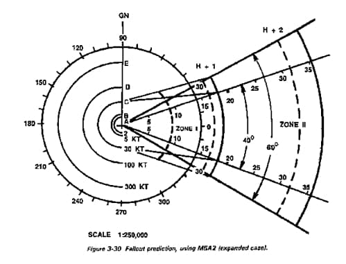
Use the M5A2 fallout predictor to make a fallout prediction. The estimated yield (16 kilotons) lies within the yield group Charlie (more than 5, not more than 30 kilotons). So, use the effective downwind direction and effective wind speed from line Charlie of the EDM; and use semicircle C on the fallout predictor. Using a yield of 16 KT and an effective wind speed of 16 kilometers per hour, read the downwind distance of Zone I (18 kilometers) from the nomogram on the predictor. Draw an arc between the radial lines of the predictor at a distance of 18 kilometers downwind from GZ (Figure 3-30). Double this distance; and draw a second arc between the radial lines of the predictor at a distance of 36 kilometers downwind from ground zero.
Draw two straight lines tangent to the 30-kiloton cloud radius semicircle, and extend them to where the Zone I arc intersects the radial lines. The area enclosed by the two lines, the 30-kilotons semicircle (40° angle), and the 18-kilometer arc, is Zone I. The area enclosed by the 18-kilometer and 36-kilometer arcs and the radial lines is Zone II. Draw a series of dashed arcs at distances equal to the product of the effective wind speed (16 kilometers per hour) and the hours of interest after the burst to represent the estimated times of arrival of fallout (16 kilometers at H + 1 and 32 kilometers at H + 2) (Figure 3-30). Arcs that fall outside Zone II need not be drawn. Draw a straight line from the center of the azimuth dial through the effective downwind direction (90 degrees) on the azimuth dial, and label the line “GN.”
Place the center of the azimuth dial on the predictor over the estimated GZ (MN553298) on the map (the scales of the map and predictor must correspond). Rotate the predictor around the GZ point until the GN line is pointing toward GN. The predictor is now oriented so that fallout is going toward 90 degrees. The area predicted to be covered by fallout can now be evaluated.
Simplified Fallout Prediction (Expanded Case)
Assume that line Charlie is the same as in the preceding example, but it also has three more digits–total of nine digits. Line Charlie now reads 090016060. Follow the same procedure as for a normal case, but expand the left and right radial lines to 60 degrees. The prediction will look like that in Figure 3-30.
Simplified Fallout Prediction (Circular Case)
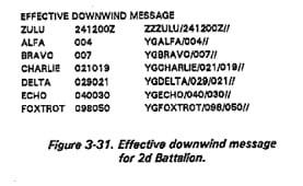
The S3, 2d Battalion, 62d Infantry, has the effective downwind message shown in Figure 3-31.
At about 1300 a nuclear burst occurred at a point estimated to be MN423876. A measurement of the cloud width and distance to GZ indicates a yield of 4 kilotons.
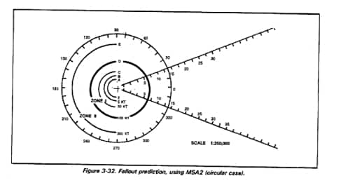
The estimated yield of 4 kilotons falls into yield group Bravo of the effective downwind message, There are only three digits in line Bravo (007). This indicates a wind speed of less than 8 kmph. It also means the prediction will have a circular pattern. On a piece of overlay paper, clear plastic, or an M5A2 predictor drawn to scale, draw a circle with a 7-kilometer radius. Label it Zone I. For Zone II, double the distance of Zone I, and draw a circle, using the same center used for Zone I. Label it Zone II. Label the prediction with GZ and date-time of detonation. The prediction is now complete (see Figure 3-32). Now, it may be placed on the map.
Ship’s Fallout Template
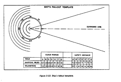
A fallout template, particularly designed for use on ships, is shown in Figure 3-33.
The ship’s fallout template is similar to the M5A2 fallout predictor (Figure 3-26) used by forces on land. The main difference is that the semicircles upwind of GZ on the ship’s fallou template do not refer to preselected weapon-yield cloud radii.
Safety Distance
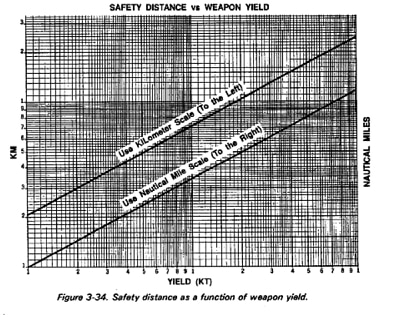
Determining the safety distance begins with determining the fallout area at a specific time after detonation. Fallout will not occur simultaneously within the predicted fallout area. It will commence in the vicinity of GZ and maybe expected to move down the fallout pattern (downwind direction) with approximately the speed of the effective wind.
The approximate zone in which deposition at the surface is taking place at a specific time after the detonation may be determined by use of the following procedures:
Step 1. Multiply the effective downwind speed by time (in hours) after the detonation.
Step 2. To the distance found in Step 1, add and subtract the safety distance obtained from the template (for the standard yield groups) or from the graph in Figure 3-34 (any yield), to allow for finite cloud size, diffusion, and wind fluctuations.
Step 3. On the plot (template), with GZ as center and the two distances obtained from 2, as radii, draw two arcs across the fallout pattern. The zone enclosed between these two arcs will, in most cases, contain the area of deposition at a specific time after the detonation.
Fallout Plotting from NAV EDM and Observations
Worked example:
A ship has received the NAV EDM shown in Figure 3-23. At 201332Z, a nuclear burst is observed from the ship, and based upon the observations taken from the ship, the yield is estimated to be 70 KT; estimated GZ is 56° 00′ N-12° 00′ E. A NAV NBC 1 nuclear report is transmitted as required; and the ship will have to prepare a fallout prediction, using the simplified procedures:
Step 1. As the yield is estimated only on the basis of the ship’s own observations, the yield estimation may not be accurate. So, to be on the safe side, the greatest yield of the yield group in which the estimated yield is contained should be used. Seventy KT is in yield group DELTA, and the largest yield in this group is 100 KT. Therefore, 100 KT will be used for the fallout prediction.
Step 2. Select the data contained in the DELTA yield group in the NAV EDM: DELTA 122016, meaning that the effective downwind direction is 122 degrees, and the effective downwind speed is 16 knots.
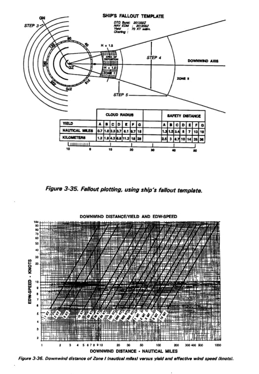
Step 3. On the template draw the GN line from GZ through 122 degrees on the compass rose see Figure 3-35.
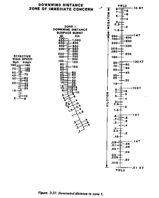
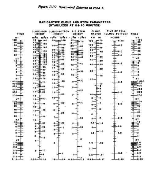
Step 4. From the graph in Figure 3-36 or the nomogram in Figure 3-37, determine the downwind distance of Zone 1 to be 30 nautical miles. Zone II downwind distance is double this distance, or 60 nautical miles from GZ, in effective downwind direction.
Step 5. Using GZ as center and the two distances, the Zone I and Zone II distances as radii (to the appropriate chart scale), draw two arcs between the radial lines. From the template or from Figure 3-38 read the cloud radius to be 3.7 nautical miles, and draw a semicircle upwind of GZ, using GZ as center and 3.7 nautical miles as radius. The preprinted semicircles may be helpful. From the intersections of the Zone I arc with the radial lines, draw lines to connect with the ends of the semicircle.
Step 6. Determine the area where deposit of fallout is estimated to take place at a specific time after the detonation Multiply the effective downwind speed by the time (hours after detonation)–l. 5 hours after the burst (H + 1.5 hours): 16 knots x 1.5 hours = 24 nautical miles.
With GZ as center and 24 nautical miles as radius, draw a dotted arc across the fallout plot. This arc represents the middle of the area within which fallout may be expected to reach the surface at H + 1.5 hours after the detonation. To allow for finite cloud size, diffusion and wind fluctuations, a certain distance ahead of and behind this line must be added to determine the area within which, in most circumstances, the fallout will be deposited at the surface at H + 1.5 hours. This is the safety distance. From the table printed on the template or from Figure 3-34, find the safety distance for yield group DELTA (100 KT) to be 5 nautical miles. Add and subtract 5 nautical miles to and from 24 nautical miles:
24 + 5 = 29 nautical miles,
and 24 – 5 = 19 nautical miles.
Using these two distances as radii and GZ as center, draw two arcs across the fallout pattern. The area confined by the two arcs and the cross wind boundaries of the fallout area defines the approximate area of fallout deposit at 1.5 hours after the detonation.
Complete the fallout prediction plot by indicating the following on the fallout template:
NAV EDM used,
Yield (estimated or actual),
GZ, and
Geographic chart number (scaling).
Fallout Plotting from NAV EDM and NAV NBC 2 Nuclear Report
Based on a number of NAV NBC 1 nuclear reports, the NBC collection/subcollection center will calculate the weapon yield, GZ, and type of burst. These data will be transmitted to naval forces/ships in the format of a NAV NBC 2 nuclear report.
Example:
NAV NBC 2 Nuclear
A
24
(strike serial number)
D
201405Z
(date-time of detonation)
F
56° 00’N–11° 15’E
(location of detonation)
H
SURFACE
(type of burst)
N
10 KT
(actual yield)
Based on the information from NAV NBC 2 nuclear report and NAV EDM, the ship will produce a fallout plot, following the principles described in the preceding paragraphs with a few adjustments:Step 1. Determine downwind distance of Zone I by using the actual yield (item N in NAV NBC 2 nuclear report as entrance figure in Figure 3-36 or Figure 3-37.
Step 2. Determine the cloud radius by using the actual yield as your entrance figure in Figure 3-38.
Step 3. Determine the safety distance by using the actual yield as entrance figure in Figure 3-34.
Step 4. When the plot has been prepared, complete the fallout prediction plot by indicating the following on the template:
NAV NBC 2 nuclear report used,
Yield, and date-time of burst,
GZ,
Geographic chart number (scaling), and
NAV EDM used.
The NBC 2 nuclear report and simplified fallout procedures are designed to give the tactical commander a quick reference or picture of the potential fallout pattern. This picture will allow the commander to plan accordingly, if the unit is within the potential fallout pattern. Such planning and preparation may include: start continuous monitoring, cover supplies and equipment (to include food and water supplies), warn adjacent and subordinate units of the potential threat, and ensure dosimeters (IM93s) are zeroed and issued to appropriate individuals.
Once the NBCC has collected sufficient data (numerous NBC 1 and 2 nuclear reports from designated units, a visual description of the crater and exact location of ground zero) the center will generate an NBC 3 nuclear report for a detailed fallout prediction. This report provides tactical units more precise data on the extent and arrival of fallout that will possibly be of operational concern.

Gordon Duff posted articles on VT from 2008 to 2022. He is a Marine combat veteran of the Vietnam War. A disabled veteran, he worked on veterans and POW issues for decades.
Gordon is an accredited diplomat and is generally accepted as one of the top global intelligence specialists. He manages the world’s largest private intelligence organization and regularly consults with governments challenged by security issues.
Duff has traveled extensively, is published around the world, and is a regular guest on TV and radio in more than “several” countries. He is also a trained chef, wine enthusiast, avid motorcyclist, and gunsmith specializing in historical weapons and restoration. Business experience and interests are in energy and defense technology.
ATTENTION READERS
We See The World From All Sides and Want YOU To Be Fully InformedIn fact, intentional disinformation is a disgraceful scourge in media today. So to assuage any possible errant incorrect information posted herein, we strongly encourage you to seek corroboration from other non-VT sources before forming an educated opinion.
About VT - Policies & Disclosures - Comment Policy

