…by Gordon Duff, Senior Editor, and the Members of the Department of Energy 9/11 Investigation Team
“Everything we are told about nuclear weapons, who makes them, how they work and what they do is a lie. If truth is an orphan, perhaps we can supply the needed parental guidance.”… Gordon Duff
_________________________________
“A very small and compact fusion-fission weapon can be made consisting of 1.5 grams of tritium and 660 grams of PU-239. This will produce sufficient neutrons to fission 120 grams of plutonium directly and 660 grams of plutonium indirectly when the secondary neutrons are taken into account. The explosive energy released from a very small fusion-fission weapon design of this size is 0.20 kt or about 200 tons of TNT. In a much larger weapon containing 4.5 kg of plutonium this would release 11.6 kt of energy. Larger total yields and higher efficiency is possible.”
…(submitted by the lead investigator for the Department of Energy’s 9/11 team) …Note: This has been edited for national security reasons. Anyone attempting to play with these formulas we suggest you put your financial affairs in order, write your final letters…and please go way out into the desert somewhere on a holiday.
___________________________
Clinton Bastin – also a Marine Officer veteran
[ Editors Note: Clinton Bastin died earlier this year, taking with him his 40 year career with the Atomic Energy C omission and the Dept. of Energy, and that motherload of knowledge we enjoyed via his briefings, and allowing us to debrief him.
But while he was here we did plenty and we owe him for bringing us up to to speed. He was a giant, a world reknowned expert and past president of the nuclear workers union put together after Chernobyl. And it was convenient with his being right here in Atlanta.
He told me once that the entire nuclear waste we have generated in the US to date would cover a football field five to six feet high. The huge volume we are dealing with now is hype, as most of it was “filler and stabilizer” material. The engineers figured 98% could have remained in constant use through proper cycling but that was completely rejected.
Development funding was required to determine the best engineering options to do it, and that is how they killed it…no funding. When the engineers fought for it that ended having an engineer at the head of the agency, and being replaced by physicist academics who had never spent a day working in any of the plants. You just can’t make this stuff up. You can’t imagine how astounded I was when he laid all this out. His bitterness toward the DoE was off the charts.
He put us onto how the politicians chose a nuclear policy that created huge ongoing profits via never ending maintenance and safety concerns over one of reusing nuclear fuel over and over which would eliminate the storage problem and the continued purchase of uranium. It seems the weapons producers did not like that approach.
The Iran nuclear weapons program hoax was what we were most interested in at the time. He destroyed everything that had been put out to the public both here and in Israel. Not only would it have taken Iran ten years minimum to complete a program, but that we would be able to tell in a variety of ways right away.
The American people and the world were poorly used here, and they deserve to get some retribution for what they were put through that was all theater used to manipulate us.
Clinton was not in the 911 loop, that came later with those who were his students and proteges. The big hoax we learned there is that nuclear proliferation concerns were also a hoax, as the US had first given Israel long ago all of our Davy Crockett nukes and the material in those warheads was used in more modern designs and eventually found their way into being used in terror bombing blamed on other parties… nasty stuff.
Davy Crockett nukes – the early days
So there have been much betrayal by our ruling class, and also the security orgs that never warned us that these weapons were basically all over the places, because they wanted to hide who had initiated it all.
And the contemporary boutique weapons designers who had worked to make cleaner, smaller, more specific target use weapons which tremendously reduced collateral damage and the radiation after effects.
They were not happy to have seen their designs used in terrorist attacks right here in US that only very high officials could have been capable of, and/or with the assistance of a country/countries that we provide nuclear weapons grade material to. The biggest national security threat to us all has been hidden from us because of who it involved.
This information is coming out now because a reknowning is now called for, a hitting of the reset button to review what was supposedly done for our national defense, and what we know now was converted into a domestic terror threat by those within. All are welcome to join in.
After all, it is your lives at stake, your families and future generations. Plus, you have paid for it all, and will continue to do so. We believe you have a right to know, as do do the loyal weapons designers and inspectors who worked to do the right thing, and are trying to do so now… Jim W. Dean ]
_________________________________
Thermobaric and neutron nuclear “engineered devices”…Department of Energy report
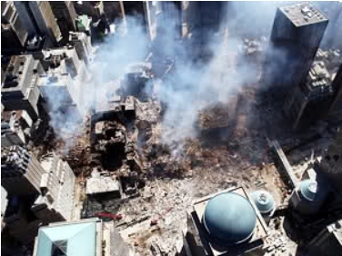
For the first time in American history, high level nuclear scientists have come forward about a massive government coverup. VT has published key sections of the highly classified 2003 DOE 9/11 Report proving the World Trade Center was destroyed by specialized nuclear munitions originating from stolen American warheads.
For those who have chosen to ignore the inexorable proofs already published, we now, with the cooperation of the DOE investigating team, publish the most comprehensive demonstration of nuclear weapons technology knowledge ever made available.
The original investigators at Ground Zero say they are no longer being silenced, that the current administration has lifted their gag orders. They have also said that their contacts inside the highest levels of the US government’s security apparatus have warned them that many “9/11 activists” are, in fact, running a sting operation, aiding the DHS and other agencies in their illegal surveillance activities.
They cite the largest and best financed groups as not gate keepers but “professional snitches.” With the bulk of 9/11 material either wild speculation or bizarre “gatekeeper” theories, the work below is our way of raising the bar to a point others can never hope to emulate.
When I contacted the DOE team, they had been following the continuing 9/11 cover up, now, according to them, being run by the “Truther” movement itself. Toward that end, “daylight” is the best way of fighting darkness. Many claim to be experts, explosives, engineering and so on. When real experts let loose, angry at the police informants and “sniffer” types, we all benefit.
The document below demonstrates how even reactor fuel can be made into powerful nuclear weapons, supplies historical context for the nuclear weapons technology and walks to the very edge of publishing the highest classified scientific secrets in the history of the world.
Editors Note: Some exact numbers and formulas have been edited for National Security reasons and may not be 100% correct.
______________________
Presentation One: A Small Nuclear Device (don’t do this at home without a trained professional supervising)
In a very small single point compression fusion-fission weapon design. The fissile core is made of plutonium and it is assembled through linear implosion. It is usually made from tungsten and uranium alloys. The use of the tungsten is to provide a high-Z material for the radiation case, and for the fuel capsule pusher/tamper. Uranium may be used simply to provide inertial mass around the core compression system, it also serves in part as the neutron reflector and tamper.
A sketch of the design is given below. The dimensions are in centimeters. They are given along the left hand and lower border of the design. All other information is edited for national security reasons.
___________________________________
0CCCCCCCCCCCCCCCCCCCCCCCCCCCCCCCCC
9CCCCCCCCCCCCCCCCCCCCCCCCCRRRRRRRRC
8CCEEEEEEEEEEEEEEEEE   RRRR    RRRRC
7CCEEEEEEEEEEEEEEEEE   RRR       RRRC
6CCEEEEEEEEEEEEEEEEE               RRC
5CCEEEEEfffffffEEEEE                RRC
4CCEEEfffffffffffEEERRRR            RRC
3CCEEfffffffffffffEERRR      HH      RC
2CCEEfffffffffffffEERR      HHHH      RC
1CCEEfffffffffffffEERR     HHHHHH     RC (pointy end ->)
0CCEEfffffffffffffEERR     HHHHHH     RC
9CCEEfffffffffffffEERR      HHHH      RC
8CCEEfffffffffffffEERRR      HH      RC
7CCEEEfffffffffffEEERRRR            RRC
6CCEEEEffffffffffEEE                RRC
5CCEEEEEEEEEEEEEEEEE               RRC
4CCEEEEEEEEEEEEEEEEE   RRR        RRC
3CCEEEEEEEEEEEEEEEEE   RRRR    RRRRC
2CCCCCCCCCCCCCCCCCCCCCCCCRRRRRRRRRC
1CCCCCCCCCCCCCCCCCCCCCCCCCCCCCCCCC
01234567890123456789012345678901234567
Legend:
C - casing (steel and uranium?)
E - explosive
f - fissile material (plutonium)
R - radiation shield/radiation case (tungsten)
H - hydrogen fuel capsule, made of tungsten, filled with D-T gas
The fissile material mass in this design would be up to 10 kg maximum. For a 750 ton fusion yield it would require at least 10 g of D-T mixture for the fusion fuel. Under high static pressure hydrogen can reach densities of around 0.1 mole/cc (0.25 g/cm^3 for DT).
This indicates a fuel capsule volume of at least 40 cm^3, with a spherical radius of 2.5-3 cm including wall thickness and a 10 cm spherical radius for the outer casing of the weapon. Note: The exact numbers are edited for national security reasons.
________________________________
Real Nuclear Weapons; Presentation Two
In the design of nuclear weapons the compression of PU-239 to above normal density (achievable factors range up to 3 or so in weapons) reduces the (critical mass) physical dimensions of the system proportionately.
In computing the effective reactivity of a system we must also take into account the rate at which neutrons are lost by escape from the system. This rate is measured by the number of neutrons lost per collision. For a given geometry, the rate is determined by the size of the core.
Put another way, for a given geometry and degree of reactivity, the size of the core is determined only by the parameter C or core compression size. The higher the value of core compression, the smaller the assembly can be. An indication of the effect of core compression on the size of a critical assembly can be gained by the following table of critical radii for a bare (unreflected) sphere:
Critical Radius (Cr) vs (c )
compression ratio                critical radius in cm.
1.0                                    infinite
1.02                                   12.027
1.05                                    7.277
1.10                                    4.873
1.20                                    3.172
1.40                                    1.985
1.60                                    1.476
If the composition, geometry, and reactivity of a system are specified then the size of a system is fixed. Therefor the physical size or scale of the system (measured in centimetres) is inversely proportional to its density. Since the mass of the system is equal to volume*density, and volume varies with the cube of the radius. To double the density of one cubic centimetre of uranium (18.9 grams) 1.7 x 10^12 ergs is required for shock compression.
This is the amount of energy found in 40 grams of TNT, about twice the weight of the uranium. The efficiency of an implosion system at transferring high explosive energy to the core is generally not better than 30%. This allows us to make a good estimate of the amount of explosive required to compress a given amount of uranium or plutonium to high density (a minimum of 6 times the mass of the fissile material for a compression factor of 2).
That is, the critical mass of a system is inversely proportional to the square of the density. C is the degree of compression (density ratio). This scaling law applies to bare cores, it also applies to cores with a surrounding reflector, if the reflectors density has an identical degree of compression.
This is usually not the case in real weapon designs, a higher degree of compression generally being achieved in the core than in the reflector. These same considerations are also valid for any other specified degree of reactivity, not just critical cores. These curves also show that very high shock compressions (four and above) are so energetically expensive as to be infeasible.
To achieve a factor of only 3, 7.1×10^11 ergs/g of uranium is required. Factoring implosion efficiency (30%), the high explosive (if it is TNT) must have a mass 56 times that of the material being compressed. Reports of compressions of four and higher can thus be safely discounted. Compression figures for plutonium above 30 kilobars, is not much different from that of uranium. Although there are large density variations from element to element at low pressure, the low density elements are also the most compressible, so that at high pressures (several megabars) the plot of density vs atomic number becomes a fairly smooth function.
This implies that what differences there may be in behavior between U and Pu at low pressure will tend to disappear in the high pressure region. Even in the low pressure region the available information shows that the difference in behavior isn’t all that great, despite the large number of phases (six) and the behavior exhibited by plutonium at atmospheric pressure.
The highest density phases of both metals have nearly identical atomic volumes at room pressure, and the number of phases of both metals drops rapidly with increasing pressure, with only two phases existing for both metals above 30 kilobars.
The lowest density phase of plutonium, the delta phase, in particular disappears very rapidly. The amount of energy expended in compression at these low pressures is trivial. The compression data for uranium is thus a good substitute for plutonium, especially at high pressures and high compressions. The shock and isentropic pressures required corresponding to the compression energy curves are shown below. The pressures shown on the X axis are in kilobars, the y axis gives the relative volume change (V/V_0).
_____________________________
Required Pressure for Shock and Isentropic Compression of Uranium
Since the compression energies of interest vary by many orders of magnitude over compressions ranging up to 3, it is often more convenient to look at logarithmic plots or energy. Figure 4.1.6.2.1-3, below, gives the isentropic curve from 10^7 ergs/cm^3 to 10^12 ergs/cm^3.
Since the energy for shock compression is virtually identical to the isentropic value at small compressions, the curve for shock compression is given for compression energies of 10^10 erg/cm^3 (V/V_0 ~ 0.9)
______________________________
Logarithmic Plot of Energy Required for Isentropic Compression of Uranium
Shock Wave Generation Systems
The only practical means of generating shock waves in weapons is through the use of high explosives. When suitably initiated, these energetic materials support detonation waves: a self-sustaining shock wave that triggers energy releasing chemical reactions, and is driven by the expanding gases that are produced by these reactions. Normally a high explosive is initiated at a single point.
The detonation propagates as a convex detonation wave, with a more or less spherical surface, from that point. To drive an implosion, a divergent detonation wave must be converted into a convergent one (or a planar one for linear implosion).
Gun Assembly.
This was the first technique to be used for creating fission explosions, and the first to be successfully developed. The first nuclear weapon to be used in war was the gun-type bomb called Little Boy, dropped on Hiroshima. Basic gun assembly is very simple in both concept and execution.
The super critical assembly is divided into two pieces, each of which is sub critical. One of these, the projectile, is propelled into the other, called the target, by the pressure of propellant combustion gases in a gun barrel. Since artillery technology is very well developed, there are really no significant technical problems involved with designing or manufacturing the assembly system.
The simple single-gun design (one target, one projectile) imposes limits on weapon, mass, and efficiency. Gun designs may be used for several applications. They are very simple, and may be used when development resources are scarce or extremely reliability is called for.
Gun designs are natural where weapons can be relatively long and heavy, but weapon diameter is severely limited – such as nuclear artillery shells (which are “gun type” weapons in two senses!) or earth penetrating “bunker busters” (here the characteristics of a gun tube – long, narrow, heavy, and strong – are ideal).
Single guns are used where designs are highly conservative (early US weapon, the South African fission weapon), or where the inherent penalties of the design are not a problem (bunker busters perhaps). Double guns are probably the most widely used gun approach (in atomic artillery shells for example).
Single Gun Systems.
A practical limit for simple gun assembly (using a single gun) is a bit less than 2 critical masses, reasoning as follows: each piece must be less than 1 critical mass, if we have two pieces then after they are joined the sum must be less than 2 critical masses. If we hollow out a super critical assembly by removing a chunk from the center like an apple core, we reduce its effective density.
Since the critical mass of a system is inversely proportional to the square of the density, we have increased the critical mass remaining material (which we shall call the target) while simultaneously reducing its actual mass.
The piece that was removed (which will be called the bullet) must still be a bit less than one critical mass since it is solid. Using this reasoning, letting the bullet have the limiting value of one full critical mass, and assuming the neutron savings from reflection is the same for both pieces we have: M_c/((M – M_c)/M)^2 = M – M_c where M is the total mass of the assembly, and M_c is the standard critical mass.
The solution of this cubic equation is approximately M = 3.15 M_c. In other words, with simple gun assembly we can achieve an assembly of no more than 3.15 critical masses. Of course a practical system must include a safety factor, and reduce the ratio to a smaller value than this. The weapon designer will undoubtedly surround the target assembly with a very good neutron reflector. The bullet will not be surrounded by this reflector until it is fired into the target, its effective critical mass limit is higher, allowing a larger final assembly than the 3.15 M_c calculated above.
Looking at U-235 critical mass tables for various candidate reflectors we can estimate the achievable critical mass ratios taking into account differential reflector efficiency. A steel gun barrel is actually a fairly good neutron reflector, but it will be thinner and less effective than the target reflector. M_c for U-235 (93.5% enrichment) reflected by 10.16 cm of tungsten carbide (the reflector material used in Little Boy) is 16.5 kg, when reflected by 5.08 cm of iron it is 29.3 kg (the steel gun barrel of Little Boy was an average of 6 cm thick).
This is a ratio of 1.78, and is probably close to the achievable limit (a beryllium reflector might push it to 2). we get: M_c/((M – (1.78 M_c))/M)^2 = M – (1.78 M_c) which has a solution of M = 4.51 M_c. If a critical mass ratio of 2 is used for beryllium, then M = 4.88 M_c.
This provides an upper bound on the performance of simple gun-type weapons. Some additional improvement can be had by adding fast neutron absorbers to the system, either natural boron, or boron enriched in B-10. A boron-containing sabot (collar) around the bullet will suppress the effect of neutron reflection from the barrel, and a boron insert in the target will absorb neutrons internally thereby raising the critical mass.
In this approach the system would be designed so that the sabot is stripped of the bullet as it enters the target, and the insert is driven out of the target by the bullet. This system was apparently used in the Little Boy weapon.
Using the M_c for 93.5% enriched U-235, the ratio M/M_c for Little Boy was (64 kg)/(16.5 kg) = 3.88, well within the limit of 4.51 (ignoring the hard-to-estimate effects of the boron absorbers). It appears then that the Little Boy design was developed with the use of >90% enrichment uranium in mind. The actual fissile load used in the weapon was only 80% enriched however, with a corresponding WC reflected critical mass of 26.5 kg, providing an actual ratio of 64/26.5 = 2.4.
The mass-dependent efficiency equation shows that it is desirable to assembly as many critical masses as possible. Applying this equation to Little Boy (and ignoring the equation’s limitations in the very low yield range) we can examine the effect of varying the amount of fissile material present:
If its fissile content had been increased by a mere 25%, its yield would have tripled.
The explosive efficiency of Little Boy was 0.23 kt/kg of fissile material (1.3%), compared to 2.8 kt/kg (16%) for Fat Man (both are adjusted to account for the yield contribution from tamper fast fission). Use of 93.5% U-235 would have at least doubled Little Boy yield and efficiency, but it would still have remained disappointing compared to the yields achievable using implosion and the same quantity of fissile material.
________________________________
Cylindrical and Planar Shock Techniques.
Cylindrical and planar shock waves can be generated using the techniques previously described, making allowances for the geometry differences. A cylindrical shock can be created using the 2-D analog of the explosive lens, a wedge shaped lens with the same cross section as the conical version. A planar shock is simply a shaped shock with zero curvature. A complete cylindrical implosion would require several parallel wedge-shaped explosive lenses arranged around the cylinder axis to form a star shape.
To make the implosion truly cylindrical (as opposed to conical) it is necessary to detonate each of these lenses along the entire apex of the wedge simultaneously. This can be done by using a lens made out of sheets of high explosive (supported by a suitable backing) to create a plane shock. The edge of this sheet lens would join the apex of the wedge.
This sheet lens need not extend out radially, it can join at an angle so that it folds into the space between the star points. Some special techniques are also available based on the peculiar characteristics of the 1-D and 2-D geometries. The basic principle for these techniques is the “flying plate line charge”, illustrated below.
A metal plate is covered on one side with a sheet of explosive. It is detonated on one edge, and the detonation wave travels across the plate. As it does so the detonation accelerates the plate, driving it to the right. After the explosive has completely detonated the flying plate will be flat again.
The angle between the original stationary plate and the flying plate is determined by the ratio between the detonation velocity, and the velocity of the accelerated plate. When this high velocity plate strikes the secondary explosive charge the shock will detonate it, creating a planar detonation.
As described above, the system doesn’t quite work. A single detonator will actually create a circular detonation front in the explosive sheet, expanding from the initiation point. This can be overcome by first using a long, narrow flying plate (a flying strip if you will) to detonate the edge of wide plate.
This wide plate can then be used to initiate the planar detonation. The flying strip approach can also be used to detonate the cylindrical lens system described above in place of the sheet lens. The flying plate scheme can be easily extended to create cylindrical detonations.
This is a cross section view of a hollow truncated cone covered by a layer of explosives. The wide end of the cone is joined to a sheet of explosives with a detonator in the center.
The single detonator located on the axis causes an expanding circular detonation in the explosive sheet. When the shock wave reaches the perimeter, it continues traveling along the surface of the cone. The cone collapses starting at the wide end. The angle of the cone is such that a cylindrical flying plate is created that initiates a cylindrical detonation in the secondary explosive.
Flying plate systems are much easier to develop than explosive lenses. Instrumentation for observing their behavior is relatively simple. Multiple contact pins and an oscilloscope can easily measure plate motion, and well established spark gap photography can image the plate effectively.
_______________________________
Explosives.
The choice of explosives in an implosion system is driven by the desire for high performance, safety, ease of fabrication, or sometimes by special properties like the slow detonation velocity needed in explosive lenses. The desire for high performance leads to the selection of very energetic explosives that have very high detonation velocities and pressures (these three things are closely correlated).
The highest performance commonly known explosive is HMX. Using HMX as the main explosive will provide the greatest compression. HMX was widely used in US weapons from the late fifties on into the 1970s, often in a formula called PBX-9404 (although this particular formulation proved to have particularly serious safety problems – causing eight fatalities in a six month period in 1959 among personnel fabricating the explosive).
HMX is known to be the principal explosive in many Soviet weapon designs since Russia is selling the explosive extracted from decommissioned warheads for commercial use. The chemically related RDX is a close second in power. It was the principal explosive used in most early US designs, in the form of a castable mixture called Composition B.
In recent years the US has become increasingly concerned with weapon safety, following some prominent accidents in which HE detonation caused widespread plutonium contamination and in the wake of repeated fatal explosions during fabrication. Many of the high energy explosives used, such as RDX and HMX, are rather sensitive to shock and heat.
While normally an impact on the order of 100 ft/sec is required to detonate one these explosives, if a sliding or friction-producing impact occurs then these explosives can be set off by an impact as slow as 10 ft/sec (this requires only a drop of 18 inches)! This has led to the use of explosives that are insensitive to shock or fire. Insensitive explosives are all based on TATB, the chemical cousin DATB lacks this marked insensitivity. These explosives have very unusual reaction rate properties that make them extremely insensitive to shock, impact, or heat.
TATB is reasonably powerful, being only a little less powerful than Comp B. A composition known as PBX-9504 has been developed that adds 15% HMX to a TATB mixture, creating a compromise between added power and added sensitivity. Another very strong explosive called PETN has not been used much (or at all) as a main explosive in nuclear weapons due to its sensitivity, although it used in detonators.
Fabricating explosives for implosion systems is a demanding task, requiring rigid quality control. Many explosive components have complex shapes, most require tight dimensional tolerances, and all require a highly uniform product. Velocity variations cannot be greater than a few percent. Achieving such uniformity means carefully controlling such factors as composition, purity, particle size, crystal structure, curing time and curing temperature.
Casting was the first method used for manufacturing implosion components since a very homogenous product can be produced in fairly complex shapes. Unfortunately the most desirable explosives do not melt, which makes casting of the pure explosive impossible. The original solution adopted by the US to this problem was to use castable mixtures of the desired explosive and TNT.
TNT is the natural choice for this, being the only reasonably powerful, easily melted explosive available. Composition B, the first explosive used, typically consisted of 63% RDX, 36% TNT, and 1% wax (cyclotol, a mixture with a higher proportion of RDX to TNT, was used later). Great care must be taken to ensure that the slurry of solid explosive and melted TNT is uniform since settling occurs.
Considerable attention must be paid to controlling the particle size of the solid explosive, and to monitoring the casting, cooling, and curing processes. Mold making is also a challenging task, requiring considerable experimentation at Los Alamos before an acceptable product could be made. Pressing is a traditional way of manufacturing explosives products, but its inability to make complex shapes, and problems with density variations and voids prevented its use during WWII.
Plastic explosives (that is – soft, pliable explosives) can be pressed into uniform complex shapes quite easily, but their lack of strength make them unattractive in practical weapon designs. During the forties and fifties advances in polymer technology led to the creation of PBXs (plastic bonded explosives).
These explosives use a polymer binder that sets during or after fabrication to make a rigid mass. The first PBX was developed at Los Alamos in 1947, an RDX-polystyrene formulation later designated PBX 9205. Some early work used epoxy binders that harden after fabrication through chemical reactions, but current plastic binders are thermosetting resins (possibly in combination with a plasticizer). Explosive granules are coated with the plastic binder and formed by pressing, usually followed by machining of the billet.
The desire for maximum explosive energy has led to the selection of polymers and plasticizers that actively participate in the explosion, releasing energy through chemical reactions. Emphasis on this has led to undesirable side effects – like sensitization of the main explosive (as occurred with PBX-9404), or poor stability.
In the 1970s the W-68 warhead, the comprising large part of the U.S. submarine warhead inventory, developed problems due to decomposition of the LX-09 PBX being used, requiring the rebuilding of 3,200 warheads. LX-09 also exhibited sensitivity problems similar to PBX-9404, in 1977 three men were killed at the Pantex plant in Amarillo from a LX-09 billet explosion.
Normally the explosive and polymer binder are processed together to form a granulated material called a molding powder. This powder is formed using hot pressing – either isostatic (hydrostatic) or hydraulic presses, using evaluated molds (1 mm pressure is typical).
The formed material may represent the final component, but normally additional machining to final specifications is required. PBXs contain a higher proportion of the desired explosive, possess greater structural strength, and also don’t melt. These last two properties make them easier to machine to final dimensions. Plastic bonding is very important in insensitive high explosives (IHEs), since mixing the insensitive explosives with the more sensitive TNT would defeat the purpose of using them.
PBX was first used in a full-scale nuclear detonation during the Redwing Blackfoot shot in June 1956. PBXs have replaced melt castable explosives in all US weapons. The PBX compositions that have been used by the U.S. include PBX-9404, PBX-9010, PBX-9011, PBX-9501, LX-04, LX-07, LX-09, LX-10, LX-11. Insensitive PBXs used are PBX-9502 and LX-17.
_______________________________
Explosive Compositions Used In U.S. Nuclear Weapons
Baratol: 76% barium nitrate, 24% TNT (typical)Low velocity castable explosive used in early explosive lenses.
Boracitol: 60% boric acid, 40% TNT (typical)Low velocity castable explosive used in later explosive lens designs.
Composition B: 63% RDX, 36% TNT, 1% wax (typical)High velocity castable main explosive used in early nuclear weapons
(e.g. Fat Man; Mks 4, 5 and 6), also MK 28 and MK 53 (latter warhead
still in service).
Cyclotol: 75% RDX, 25% TNTHigh velocity castable main explosive, basically just Comp B with a
higher RDX content for higher performance. Used in MK 28 and MK-53
(latter warhead still in service). Substituted for PBX-9404 when
unacceptable sensitivity problems arose.
LX-04: 85% HMX, 15% Viton AHigh velocity PBX main explosive. Used in W-62 and W-70.
LX-07: 90% HMX, 10% Viton AHigh velocity PBX main explosive. Used in W-71.
LX-09: 93% HMX, 4.6% pDNPA, 2.4% FEFOHigh velocity PBX. Main explosive used in the W-68 warhead. Withdrawn
from use due to aging problems (binder/plasticizer exudation). Serious
safety problems.
LX-10: 95% HMX, 5% Viton A; and LX-10-1: 94.5% HMX, 5.5% Viton AHigh velocity PBX main explosive. Replaced LX-09 in W-68. Also used in
W-70; W-79; and W-82.
LX-11: 80% HMX, 20% Viton AHigh velocity PBX main explosive. Used in W-71.
LX-17: 92.5% TATB, 7.5% Kel-F 800High velocity insensitive PBX. One of two IHEs in use. Used in B-83;
W-84; W-87; and W-89. Stockpile-monitoring of the W87 warhead shows
some evidence of stiffening with age, perhaps due to an increase in the
crystallinity of the binder.
PBX-9010: 90% RDX, 10% Kel-FHigh velocity PBX main explosive. Used in MK 43 and W-50.
PBX-9011: 90% HMX, 10% EstaneHigh velocity PBX main explosive. Used in MK 57 Mods 1 and 2.
PBX-9404: 94% HMX, 3% NC, 3% CEFHigh velocity PBX main explosive. Widely used – MK 43; W-48; W-50;
W-55; W-56; MK 57 Mod 2; MK/B 61 Mods 0, 1, 2, 5; and W-69. Serious
safety problems.
PBX-9501: 95% HMX, 2.5% Estane, 2.5% BDNPA-FHigh velocity PBX main explosive. Used in W-76; W-78; and W-88.
PBX-9502: 95% TATB, 5% Kel-FHigh velocity insensitive PBX. Principal IHE in recent US weapon
designs, currently being backfitted to earlier warheads replace other
plastic bonded explosives. Used in B-61 Mods 3, 4, 6-10; W-61; W-80;
W-85; W-90; and W-91.
Plumbatol: 70% lead nitrate, 30% TNT (typical)The use of this low velocity castable explosive in US nuclear weapons
is speculative.
Explosives And Binder Ingredients Used In U.S. Nuclear Weapons
Barium nitrate: Heavy metal oxidizer used in baratol slow explosive mixture.
BDNPA-F: Liquid polymer/plasticizer mixture used in PBX compositions. 50% bis(2,2-dinitropropyl), 50% acetal/bis(2,2-dinitropropyl) formal (plasticizer)
Boric Acid: Low density, low atomic number inert material used inboracitol slow explosive mixture.
CEF: Plasticizer used in PBX mixtures. tris-beta-chloroethylphosphate.
DATB: Main high explosive, insensitive. 2,4,6-trinitro-1,3-benzenediamine; also called DATNB, diamino trinitrobenzene.
DNPA (pDNPA): Solid explosive used in a binder mixture. 2,2-dinitropropyl acrylate.
FEFO: Liquid explosive used in a binder mixture. 1,1-[methylenebis(oxy)]-bis-[2- fluoro-2,2-dinitroethane].
HMX: Main high explosive, very powerful. Octahydro-1,3,5,7-tetranitro-1,3,5,7- tetrazocine; also called beta-HMX, octogen, cyclotetramethylene tetranitramine, (HMX is WWII code name, from His Majesty’s eXplosive). Dual use material, export restricted.
HNS: Relatively insensitive, a very heat stable high explosive, used in slapper detonators. 1,1′-(1,2-ethylenediyl) bis-(2,4,6-trinitrobenzene); also called hexanitrostilbene. Dual use material, export restricted.
Lead nitrate Heavy metal oxidizer used in plumbatol slow explosive mixture.
NC: Solid explosive used as a plastic binder. Nitrocellulose.
PETN: Sensitive powerful high explosive, used in detonators. 2,2- bis[(nitroxy)methyl]-1,3-propanediol dinitrate; also called pentaerythritol tetranitrate.
RDX: Main high explosive, powerful. hexahydro-1,3,5-trinitro-1,3,5-triazine; also called cyclonite, hexogen. Dual use material, export restricted.
TATB: Main high explosive, very insensitive and heat stable. Special fine-grained TATB used in boosters. 2,4,6-trinitro-1,3,5-benzenediamine; also called TATNB,
triaminotrinitrobenzene. Dual use material, export restricted. Produced on an industrial scale in the U.S. at a cost of $90 to $250/kg. Currently available to customers outside DOE for about $200/kg.
TNT: Main high explosive, used as a meltable binder. 2-methyl-1,3,5- trinitrobenzene; also called trinitrotoluene.
Viton A: Rubbery solid used as a plastic binder. Copolymer consisting of 60% Vinylidine fluoride/40% hexafluoropropylene.
Since shock waves inherently compress the material through which they pass, an obvious way of using the implosion wave is simply to let it pass through the fissile core, compressing it as it converges on the center. This technique can (and has) been used successfully, but it has some inherent problems not all of which can be remedied.
First, the detonation pressure of available explosives (limit 400 kilobars) is not high enough for much compression. A 25% density increase is all that can be obtained in uranium at this pressure, delta-phase plutonium can reach 50% due to the low pressure delta->alpha phase transformation. This pressure can be augmented in two ways: by reflecting the shock at high impedance interfaces, and by convergence.
Since the fissile material is about an order of magnitude denser than the explosive itself, the first phenomenon is certain to occur to some extent. It can be augmented by inserting one or more layers of materials of increasing density between the explosive and the dense tamper and fissile material in the center. As a limit, shock pressure can double when reflected at an interface. To approach this limit the density increase must be large, which means that no more than 2 or 3 intermediate layers can be used.
The second phenomenon, shock convergence, is limited by the ratio of the fissile core radius to the outer radius of the implosion hardware. The intensification is approximately proportional to this ratio. A large intensification thus implies a large diameter system – which is bulky and heavy.
Another problem with the solid pit design is t he existence of the Taylor wave, the sharp drop in pressure with increasing distance behind the detonation front. This creates a ramp-shaped shock profile: a sudden jump to the peak shock pressure, followed by a slope down to zero pressure a short distance behind the shock front.
Shock convergence actually steepens the Taylor wave since the front is augmented by convergence to a greater degree than the material behind the front (which is at a larger radius). If the Taylor wave is not suppressed, by the time the shock reaches the center of the fissile mass, the outer portions may have already expanded back to their original density.
The use of intermediate density “pusher” layers between the explosive and the tamper helps suppress or flatten the Taylor wave. The reflected high pressure shock reinforces the pressure behind the shock front so that instead of declining to zero pressure, it declines to a pressure equal to the pressure jump at the reflection interface. That i s, if P is the initial shock pressure, and P -> 0 indicates a drop from P to zero through the Taylor wave, then the reflection augments both by p:(P + p) -> (0 + p).
The Gadget/Fat Man design had an intermediate aluminum pusher between the explosive and the uranium tamper, and had a convergence factor of about 5. As a rough estimate, one can conclude that the 300 kilobar pressure of Composition B could be augmented by a factor of 4 by shock reflection (doubling at the HE/Al interface, and the Al/U interface), and a factor of 5 by convergence, leading to a shock pressure of 6 megabars at the plutonium core.
Assuming an alpha phase plutonium equation of state similar to that of uranium this leads to a compression of a bit less than 2, which when combined with the phase transformation from delta to alpha gives a maximum density increase of about 2.5. The effective compression may have been significantly less than this, but it is generally consistent with the observed yield of the devices.
_______________________________
Levitated Core Designs
In the solid pit design, the Taylor wave is reduced but not eliminated. Also, the kinetic energy imparted by the convergent shock is not efficiently utilized. It would be preferable to achieve uniform compression throughout the fissile core and tamper, and to be able to make use of the full kinetic energy in compressing the material (bringing the inward motion of material in the core to a halt at the moment of maximum compression).
This can be accomplished by using a shell, or hollow core, instead of a solid one (see Section 3.7.4 Collapsing Shells). The shell usually consists of an outer layer of tamper material, and an inner layer of fissile material. When the implosion wave arrives at the inner surface of the shell, the pressure drops to zero and an unloading wave is created.
The shock compressed material (which has also been accelerated inward) expands inward to zero pressure, converting the compression energy into even greater inward directed motion (approximately doubling it). In this way energy loss by the outward expansion of material in the Taylor wave region is minimized.
Simply allowing this fast imploding hollow shell to collapse completely would achieve substantial compression. In practice this is never done. It is more efficient to allow the collapsing shell to collide with a motionless body in the center (the “levitated core”), the collision creating two shock waves – one moving inward to the center of the stationary levitated core (accelerating it inward), and one moving outward through the imploding shell (decelerating it).
The pressure between these two shocks is initially constant so that when the converging shock reaches the center of the core, the region extending from the center out to the location of expanding shock has achieved reasonably even and efficient compression.
I use word “reasonably” because the picture is a bit more complicated tha n just described. First, by the time the shell impacts the levitated core it has acquired the character of a thick collapsing shell. The inner surface will be moving faster than the outer surface, and a region close to the inner surface will be somewhat compressed. Second, the inward and outward moving shocks do not move at constant speed.
The inward moving shock is a classical converging shock with a shock velocity that accelerates and strengthens all the way to the center. The outward moving shock is a diverging or expanding shock that slows down and weakens.
In the classical converging shock region (the levitated core, and the innermost layer of the colliding shell) high compression is achieved and the material is brought to a halt when the shock reaches the center. In the outer diverging region, only about half of the implosion velocity is lost when the diverging shock compresses and decelerates it, and there is insufficient time for inward flow to bring it to a halt before the converging shock reaches the center.
Thus the outer region is still collapsing (slowly) when the inner shock reaches complete convergence (assuming that the outer shock has not yet reached the surface of the pit (tamper shell plus core) and initiated an inward moving release wave).
Immediately after the converging shock reaches the center, the shock rebound begins. This is an outward moving shock that accelerates material away from the center, creating an expanding low density region surrounded by a layer compressed to an even greater degree than in the initial implosion. Once the rebound shock expands to a given radius the average density of the volume within that radius falls rapidly.
For a radius well outside the classical converging shock region, the true average density may continue to increase due to the continuing collapse of the outer regions until the rebound shock arrives. The structure of the shell/core system at the time of rebound shock a rrival is actually hollow – a low density region in the center with a highly compressed shell, but the average density is at a maximum.
Whether this configuration is acceptable or not depends on the weapon design, it may be acceptable in a homogeneous un-boosted core but will not be acceptable in a boosted or a composite core design where high density at the center is desired.
Since the divergence of the outward shock is not great, and it is offset somewhat by the slower collapse velocity of the outer surface of the thick shell, we can treat it approximately as a constant speed shock traversing the impacting shell. The converging shock can be treated by the classical model (see Section 3.7.3 Convergent Shocks). This allows us to estimate the minimum shell/levitated core mass ratio for efficient compression, the case in which the shock reaches the surface of the shell, and the center simultaneously.
______________________________
If the shell and levitated core have identical densities and compressibilities, then the two shocks will have the same initial velocity (the velocity change behind the shock front in both cases will be exactly half the impact velocity). If the shell has thickness r_shell, then the shock will traverse the shell in time:
t_shell = r_shell/v
If the levitated core has radius r_lcore, the shock will reach the center in time:
t_lcore = (r_lcore/v)*alpha
Alpha is this case is the convergent shock scaling parameter (see Section 3.7.3). For a spherical implosion, and a gamma of 3 (approximately correct for most condensed matter, and for uranium and plutonium in particular), alpha is equal to 0.638 (the exact value will be somewhat higher than this).
Since we want t_shell = t_lcore:
That is, the thickness of the shell is smaller than the radius of the core by a factor of 0.638. But since volume is proportional to the cube of the radius:
Thus we want the impacting shell to have at least 3.4 times as much mass as the levitated core. The ratio used may be considerably larger.
Now it is important to realize that in principle the shell/levitated core mass ratio is unrelated to the tamper/fissile material mass ratio. The boundary between tamper and fissile material can be located in the shell (i.e. the shell is partly tamper and partly fissile, the levitated core entirely fissile), it can be located between the shell and core (i.e. the shell is tamper and the core is fissile), or it can be located in the core (i.e. the shell is tamper, and the core is partly tamper and partly fissile). The tamper/fissile material ratio is determined by neutron conservation, hydrodynamic confinement, and critical mass considerations.
It appears however that the initial practice of the US (starting with the Mk4 design and the Sandstone test series) was to design levitated core weapons so that the shell was the uranium tamper, and the levitated portion was a solid fissile core. The mass of the tamper would have been similar to that used in the Gadget (115 kg), a large enough mass to allow the use of different pit sizes and compositions while ensuring sufficient driver mass.
These early pure fission bombs were designed to use a variety of pits to produce different yields, and to allow the composition (U-235/Pu-239 ratio) to be varied to match the actual production schedules of these materials.
Levitation is achieved by having some sort of support structure that will not disrupt the implosion symmetry. The most widely used approach seems to be the use of truncated hollow cones (or conically tapered thin walled tubes if you prefer), usually made out of aluminum. Six of these are used, pairs on opposite sides of the levitated core for each axis of motion. Supporting wires (presumably under tension) have also been used.
The levitated core of the Hurricane device (the first British test) used “caltrops” (probably six of them) for support. A caltrops is a four pronged device originally used in the Middle Ages as an obstacle against soldiers and horses, and more recently against vehicle tires.
Each of the prongs can be thought of as the vertex of a tetrahedron, with the point where they all join as the tetrahedral center. A caltrops has the property that no matter how you drop it, three of the prongs forms a tripod with the fourth prong pointed straight up. Dimples on the core might be used to seat the support prongs securely.
Another possibility is to use a strong light weight foam to fill the gap between shell and core (such foams have been produced at the Allied-Signal Kansas City Plant). A significant problem with using a foam support is that plastic foams are usually excellent thermal insulators, which could cause severe problems from self-heating in a plutonium levitated core.
A serious problem with hollow shell designs is the tensile stress generated by the Taylor wave (see Section 3.6.1.1.2 Free Surface Release Waves in Solids). As the release wave moves out from the inner shell surface, it encounters declining pressure due to the Taylor wave. The “velocity doubling” effect generates a pressure drop equal in magnitude to the shock peak pressure.
If the pressure that the release wave encounters is below this pressure, a negative pressure (tension) is created (you can think of this as the faster moving part of the plate pulling the slower part along). This tensile stress builds up the farther back the release wave travels. If it exceeds the strength of the material it will fracture or “spall”. This can cause the entire inner layer of material to peel off, or it may simply create a void. A new release wave will begin at the spall surface.
Spalling disrupts implosion symmetry and can also ruin the desired collision timing. It was primarily fears concerning spalling effects that prevented the use of levitated core designs in the first implosion bombs. One approach to dealing with spalling is simply to make sure that excessive tensile stresses do not appear in the design. This requires strong materials, and at least one of the following:
relatively weak implosion pressures;
a highly suppressed Taylor wave; or
thin shells.
The first option is extremely undesirable, but the latter two can be used in viable designs.
Another approach is to adopt the “if you can’t beat’em, join’em” strategy. Instead of trying to prevent separation in the shell, accommodation for the phenomenon is included in the design. This can be done by constructing the shell from separate layers. When the release wave reaches the boundary between shell layers (and tensile stress exists at that point), the inner layer will fly off the outer layer, and a new release wave will begin. This will create a series of imploding shells, separated by gaps.
As each shell layer converges toward the center, the inner surface will accelerate while the outer surface will decelerate. This will tend to bring the layers back together. If they do not rejoin before impact occurs with the core, a complicated arrangement of shocks may develop. The design possibilities for using these multiple shocks will not be considered here.
The concept of the levitated core and colliding shells can be extended to multiple levitation – having one collapsing shell collide with a second, which then collides with the levitated core. The outer shell, due to the concentration of momentum in its inner surface and the effects of elastic collision, could enhance the velocity of the inner shell. This idea requires a large diameter system to be practical.
It is possible that the “Type D” pit (that is, the hardware located between the explosive and fissile core) developed in the early fifties for the 60 inch diameter HE assemblies then in the US arsenal was such a system. It considerably increased explosive yields with identical cores.
It seems almost certain that the most efficient kiloton range pure fission bomb ever tested – the Hamlet device detonated in Upshot-Knothole Harry (19 May 1953) – used multiple levitation. It was described as being the first “hollow core” device, presumably the use of a fissile core that itself was an outer shell and an inner levitated core. A TX-13D bomb assembly (a 60 inch implosion system using a Type D pit) was used with the core. The yield was 37 kt.
___________________________________
Thin Shell (Flying Plate) Designs
Thin shell, or flying plate designs, take the hollow core idea to an extreme. In these designs a very thin, but relatively large diameter shell is driven inward by the implosion system. As with the regular hollow core design, a levitated core in the center is used.
The advantages of a flying plate design are: a greatly increased efficiency in the utilization of high explosive energy; and a higher collision speed – leading to faster insertion and greater compression for a given amount of explosive. Thin shell flying plate designs are standard now in the arsenals of the nuclear weapon states.
A thin plate, a few millimeters thick, is thinner than the Taylor wave of an explosive shock. The shock acceleration, followed by full release, is completed before the Taylor wave causes a significant pressure drop. The maximum initial shock acceleration is thus achieved.
Even greater energy transfer than this occurs however. When the release wave reaches the plate/explosive interface (completing the expansion and velocity doubling of the plate), a rarefaction wave propagates into the explosive gases. The gases expand, converting their internal energy into kinetic energy, and launching a new (but weaker) shock into the plate.
A cyclic process thus develops in which a series of shocks of diminishing magnitude accelerate the plate to higher and higher velocities. If viewed from the inner surface, the observer would see a succession of velocity jumps of diminishing size and at lengthening intervals. The plate continues to accelerate over a distance of a few centimeters.
The maximum velocity achievable by this means can approach the escape velocity of the explosive gases, which is 8.5 km/sec for Comp B. Velocities up to 8 km/sec have been reported using HMX-based explosives. This can be compared to the implosion velocity of the plutonium pit in the Gadget/Fat Man design, which was some 2 km/sec.
Optimum performance is found when a small gap (a few mm) separates the high explosive from the plate. Among other things, this gap reduces the strength of the Taylor wave. The gap may be an air space, but it is usually filled with a low impedance material (like a plastic).
The mass ratio between the explosive and the plate largely determines the system performance. For reasonable efficiency it is important to have a ratio r of at least 1 (HE mass/plate mass). At r=1 about 30% of the chemical energy in the explosive is transferred to the plate. Below r=1, the efficiency drops off rapidly. Efficiency reaches a maximum at r=2, when 35% of the energy is transferred.
Since a higher mass ratio means more energy available, the actual final velocity and energy in the plate increases monotonically with r, as shown in the table below. Higher values of r also cause the plate to approach its limiting value with somewhat shorter travel distances.
Flying Plate Drive Efficiency
Plate/HE Mass Ratio (R)
Energy Fraction Transferred
Relative Velocity
Plate/Detonation Velocity Ratio
0.25
0.16
1.00
0.07
0.50
0.22
1.65
0.12
1.00
0.30
2.74
0.20
2.00
0.35
4.18
0.30
5.00
0.30
6.12
0.40
7.00
–
7.65
0.50
10.00
0.25
7.91
0.56
40.00
0.11
10.60
0.75
_________________________________
By the time the flying plate converges from a radius of 10-20 cm to collide with the levitated core, it is no longer a thin shell. The velocity difference that is inherent in thick shell collapse leads to a collision velocity of the inner surface that is higher than the average plate velocity. Collision velocities of experimental uranium systems of 8.5 km/sec have been reported.
The flying plate can be used in a variety of ways. It can be the collapsing shell of a levitated core design. Or it can be used as a driver which collides with, and transfers energy to a shell, which then implodes on to a levitated core. Combined Tamper/Reflector Systems By the time the flying plate converges from a radius of 10-20 cm to collide with the levitated core, it is no longer a thin shell.
The velocity difference that is inherent in thick shell collapse leads to a collision velocity of the inner surface that is higher than the average plate velocity. Collision velocities of experimental uranium systems of 8.5 km/sec have been reported.
Cylindrical Implosion Comparison of Reflector Materials Below is a list of candidate materials, and their atomic densities. The list includes the six highest atomic density pure elements (C – in two allotropic forms, Be, Ni, Co, Fe, and Cu), and a number of compounds that are notable for having high atomic densities. Atomic densities for the major tampers materials are also shown.
Highly Enriched Uranium (HEU)Highly enriched uranium (HEU) is produced by processing natural uranium with isotopic separation techniques. Natural uranium consists of 99.2836% U-238, 0.7110% U-235, and 0.0054% U-234 (by mass). Enrichment processes increase the proportion of light isotopes (U-235 and U-234) to heavy ones (U-238). Enriched uranium thus contains a higher percentage of U-235 (and U-234) than natural uranium, but all three isotopes are always present in significant concentrations.
The term “HEU” usually refers to uranium with a U-235 of 20% or more. Uranium known to have been used in fission weapon designs ranges in enrichment from 80-93.5%. In the US uranium with enrichment around 93.5% is sometimes called Oralloy (abbreviated Oy) for historical reasons (Oralloy, or Oak Ridge ALLOY, was a WWII codename for weapons grade HEU). As much as half of the US weapon stockpile HEU has an enrichment in the range of 20-80%. This material is probably used in thermonuclear weapon designs.
The flying plate can be used in a variety of ways. It can be the collapsing shell of a levitated core design. Or it can be used as a driver which collides with, and transfers energy to a shell, which then implodes on to a levitated core.
The discussion of implosion has implicitly assumed a spherically symmetric implosion since this geometry is the simplest, and also the most efficient and widely used. Few changes are needed though to translate the discussion above to cylindrical geometry.
The changes required all relate to the differences in shock convergence in cylindrical geometry. There is a much lower degree of energy focusing during shock convergence, resulting in lower pressure increase for the same convergence ratio (reference radius/inner radius). A cylindrical solid core system would thus be much less effective in generating high pressures and compressions.
For a levitated core design, the shell/levitated core mass ratio must be recalculated. The appropriate value for alpha is 0.775 in this case, but the volume only increases by r^2, so:
m_shell/m_lcore = ((1.775)^2 - 1^2)/1^2 = 2.15
___________________________________
The possibility of producing cylindrical implosion by methods that do not work for spherical geometries deserves some comment however. The flying plate line charge systems described above (4.1.6.2.2.4 Cylindrical and Planar Shock Techniques) for initiating a cylindrical implosion shocks in high explosives can be used to drive flying plates directly.
Such a single-stage system would probably not be capable of generating as fast an implosion as a two stage system; one in which the first plate initiates a convergent detonation which then drives a second flying plate. A single stage system would be simpler to develop and build, and potentially lighter and more compact however.
Cylindrical implosion systems are easier to develop that spherical ones. This largely because they are easier to observe. Axial access to the system is available during the implosion, allowing photographic and electronic observation and measurement. Cylindrical test systems were used to develop the implosion lens technology at Los Alamos that was later applied to the spherical bomb design.
Planar Implosion
Planar implosion superficially resembles the gun assembly method – one body is propelled toward another to achieve assembly. The physics of the assembly process is completely different however, with shock compression replacing physical insertion. The planar implosion process is some two orders of magnitude faster than gun assembly, and can be used with materials with high neutron background (i.e. plutonium).
By analogy with spherical and cylindrical implosion, the natural name for this technique might be “linear implosion”. This name is used for a different approach discussed below in Hybrid Assembly Techniques.
Most of the comments made above about implosion still apply after a fashion, but some ideas, like the levitated core, have little significance in this geometry. Planar implosion is attractive where a cylindrical system with a severe radius constraint exists.
Shock wave lenses for planar implosion are much easier to develop than in other geometries. A plane wave lens is used by itself, not as part of a multi-lens system. It is much easier to observe and measure the flat shock front, than the curved shocks in convergent systems. Finally, flat shocks fronts are stable while convergent ones are not. Although they tend to bend back at the edges due to energy loss, plane shock fronts actually tend to flatten out by themselves if irregularities occur.
Complex Guns
Additional improvements in gun system performance are possible by combining implosion with gun assembly. The implosion system here would be a very weak one – a layer of explosive to collapse a ring of fissile material or dense tamper on to the gun assembled core. This would allow further increases in the amount of fissile material used, and generate modest efficiency gains through small compression factors. A significant increase in insertion speed is also possible, which may be important where battlefield neutron sources may cause predetonation (this may make the technique especially attractive for artillery shell use). Complex gun approaches have reportedly been used in Soviet artillery shell designs.
Linear Implosion
In weapons with severe size (especially radius) and mass constraints (like artillery shells) some technique other than gun assembly may be desired. For example, plutonium cannot be used in guns at all so a plutonium fueled artillery shell requires some other approach.
A low density, non-spherical, fissile mass can be squeezed and deformed into a supercritical configuration by high explosives without using neat, symmetric implosion designs. The technique of linear implosion, developed at LLNL, apparently accomplishes this by embedding an elliptical or football shaped mass in a cylinder of explosive, which is then initiated at each end. The detonation wave travels along the cylinder, deforming the fissile mass into a spherical form. Extensive experimentation is likely to be required to develop this into a usable technique.
Three physical phenomenon may contribute to reactivity insertion:
density increase due to collapsing voids in the core;
density increase from phase transformations (if delta-phase plutonium is used); and
reduction in surface area by deformation into a sphere (or approximate sphere).
Since the detonation generated pressure are transient, and affect different parts of the mass at different times, compression to greater than normal densities do not occur. The reactivity insertion then is likely to be rather small, and weapon efficiency quite low (which can be offset by boosting). The use of metastable delta-phase plutonium alloys is especially attractive in this type of design. A rather weak impulse is sufficient to irreversibly collapse it into the alpha phase, giving a density increase of 23%.
The supercritical mass formed by linear implosion is stable – it does not disassemble or expand once the implosion is completed. This relieves the requirement for a modulated neutron initiator, since spontaneous fission (or a calibrated continuous neutron source) can assure detonation. If desired, a low intensity initiator of the polonium/beryllium type can no doubt be used.
Special initiation patterns may be advantageous in this design, such as annual initiation – where the HE cylinder is initiated along the rim of each end to create a convergent shock wave propagating up the cylinder.
Nuclear Design Principles
The design of the nuclear systems of fission weapons naturally divides into several areas – fissionable materials, core compositions, reflectors, tampers, and neutron initiating techniques.
Fissile Materials
In the nuclear weapons community a distinction is made between “fissile” and “fissionable”. Fissile means a material that can be induced to fission by neutrons of energy – fast or slow. These materials always have fairly high average cross sections for the fission spectrum neutrons of interest in fission explosive devices. Fissionable simply means that the material can be induced to fission by neutrons of a sufficiently high energy. As examples, U-235 is fissile, but U-238 is only fissionable.
There are three principal fissile isotopes available for designing nuclear explosives: U-235, Pu-239, and U-233. There are other fissile isotopes that can be used in principle, but various factors (like cost, or half-life, or critical mass size) that prevent them from being serious candidates. Of course none of the fissile isotopes mentioned above is actually available in pure form. All actual fissile materials are a mixture of various isotopes, the proportion of different isotopes can have important consequences in weapon design.
The techniques which have actually been used for producing HEU are gaseous diffusion, gas centrifuges, electromagnetic enrichment (Calutrons), and aerodynamic (nozzle/vortex) enrichment. Other enrichment processes have been used, some even as part of an overall enrichment system that produced weapons grade HEU, but none are suitable for the producing the highly enriched product. The original HEU production process used by the Manhattan Project relied on Calutrons, these were discontinued at the end of 1946. From that time on the dominant production process for HEU throughout the world has been gaseous diffusion. The vast majority of the HEU that has been produced to date, and nearly all that has been used in weapons, has been produced through gaseous diffusion. Although it is enormously more energy efficient, the only countries to have built or used HEU production facilities using gas centrifuges has been the Soviet Union, Pakistan, and The United Kingdom. Pakistan’s production has been very small, the United Kingdom apparently has never operated there facility for HEU production.
High enrichment is important for reducing the required weapon critical mass, and for boosting the maximum alpha value for the material. The effect of enrichment on critical mass can be seen in the following table:
 Uranium Critical Masses for Various Enrichment and Reflectors
total kg/U-235 content kg (density = 18.9)
Enrichment       Reflector
(% U-235)  None        Nat. U       Be
                       10 cm      10 cm
93.5      48.0/44.5  18.4/17.2  14.1/13.5
90.0      53.8/48.4  20.8/18.7  15.5/14.0
80.0      68. /54.4  26.5/21.2  19.3/15.4
70.0      86. /60.2  33. /23.1  24.1/16.9
60.0     120  /72.   45. /27.   32. /19.2
50.0     170  /85.   65. /33.   45. /23.
40.0     250 /100   100  /40.   70. /28.
30.0     440 /132   190  /57.  130  /39.
20.0     800 /160   370  /74   245  /49.
The total critical mass, and the critical mass of contained U-235 are both shown. The increase in critical mass with lower enrichment is of course less pronounced when calculated by U-235 content. Even with equivalent critical masses present, lower enrichment reduces yield per kg of U-235 by reducing the maximum alpha. This is due to the non-fission neutron capture cross section of U-238, and the softening of the neutron spectrum through inelastic scattering (see the discussion of U-238 as a neutron reflector below for more details about this).
U-238 has a spontaneous fission rate that is 35 times higher than U-235. It thus accounts for essentially all neutron emissions from even the most highly enriched HEU. The spontaneous fission rate in uranium (SF/kg-sec) of varying enrichment can be calculated by:
SF Rate = (fraction U-235)*0.16 + (1 - (fraction U-235))*5.5
For 93.5% HEU this rate (0.5 n/sec-kg) is low enough that large amounts can be used in weapon designs without concern for predetonation. If used in the Little Boy design (which actually used 80% enriched uranium, however) it would produce only one neutron every 31 milliseconds on average. No problem exists for any design up to the limiting size of gun-type weapons. 50% HEU on the other hand would be difficult to use in a gun-type weapon. A beryllium reflector would minimize the mass (and thus the amount of U-238 present), but to have a reasonable amount HEU present (e.g. 2.5 critical masses) would produce one neutron every 3.2 milliseconds, making predetonation a significant prospect. The rate is never high enough though to make a significant difference for implosion assembly. Plutonium
Plutonium is produced by neutron bombardment of U-238, which captures a neutron to form U-239. The U-239 then decays into neptunium-239, which decays in turn to for
m Pu-239. Since the vast majority of nuclear reactors use low enriched uranium fuel (< 20% U-235, 3-4% typically for commercial reactors), they also contain large amounts of U-238. Plutonium production is thus an inevitable consequence of operation in most reactors.
Pu-239 is the principal isotope produced, and is the most desired isotope for use in weapons or as a nuclear fuel. Multiple captures and other side reactions invariably produce an isotope mixture however. The principal contaminating isotope is always Pu-240, formed by non-fission neutron capture by Pu-239. The exposure of U-238 to neutron irradiation is measured by the fuel “burn-up”, the number of megawatt-days (thermal) per tonne of fuel. The higher the burn-up, the greater the percentage of contaminating isotopes. Weapon production reactors use fuel burn-ups of 600-1000 MWD/tonne, light water power reactors have a typical design burn-up of 33000 MWD/tonne, and have been pushed to 45000 MWD/tonne by using higher enrichment fuel.
Plutonium is commonly divided into categories based on the Pu-240 content:
< 3% Super grade
3-7% Weapons grade (normally 6-6.5%)
7-19% Fuel grade
> 19% Reactor grade (spent fuel of LW power reactors)
The first US plutonium weapon (Fat Man) used plutonium with a Pu-240 content of only 0.9%, largely due to the hurried production schedule (only 100 MWD/tonne irradiations were used to get the plutonium out of the pile and into bombs quickly). Modern US nuclear weapons use weapons grade plutonium with a nominal 6.5% Pu-240 content. A lower Pu-240 content is not necessary for correct weapon functioning and increases the cost. The US has produced low-burnup supergrade plutonium to blend with higher burn-up feedstocks to produce weapons grade material. Plutonium produced in power reactors varies in composition, but its isotope profile remains broadly similar. If U-238 is exposed to extremely high burn-ups as in some fast breeder reactor designs (100,000 MWD/tonne), or if plutonium is separated from spent fuel and used as fuel in other reactors, it tends toward an equilibrium composition.
Representative plutonium compositions are:
These isotopes do not decay at the same rate, so the isotopic composition of plutonium changes with time (this is also true of HEU, but the decay process there is so slow as to be unimportant). The shortest lived isotopes found in weapon, fuel, or reactor grade plutonium in significant quantities are Pu-241 (13.2 yr) and Pu-238 (86.4 yr). The other isotopes have half-lives in the thousands of years and thus undergo little change over a human lifespan. The decay of Pu-241 (to americium-241) is of particular significance in weapons, since weapons grade plutonium contains no Pu-238 to speak of.
To understand the significance of these composition variations, we need to look at two principal factors: the critical mass size, and the spontaneous fission rate. An additional factor, decay self-heating, will be considered but is much less important.
Below are the estimated bare (unreflected) critical masses (kg) for spheres of pure plutonium isotopes in the alpha phase (and americium-241, since it is formed in weapons grade plutonium):
Pu-238   9 kg
Pu-239  10 kg
Pu-240  40 kg
Pu-241  12 kg
Pu-242  90 kg
Am-241 114 kg
The most striking thing about this table is that they all have critical masses! In contrast U-238 (or natural uranium, or even LEU) has no critical mass since it is incapable of supporting a fast fission chain reaction. This means that regardless of isotopic composition, plutonium will produce a nuclear explosion if it can be assembled into a supercritical mass fast enough.
Next observe that the critical masses for Pu-239 and Pu-241 are nearly the same, while the critical masses for Pu-240 and 242 are both several times higher. Because of this disparity, Pu-239 and Pu-241 tend to dominate the fissionability of any mixture, and it is commonplace in the literature to talk about these two isotopes as “fissile”, while Pu-240 and 242 are termed “non-fissile”. However it is not really true that 240 and 242 are non-fissile, which has an important consequence (shown in the table below):
We can see that while the critical mass increases with declining “fissile” isotope content, the mass of Pu-239 present in each critical system diminishes. This is the exact opposite of the effect of isotopic dilution in uranium. In the range of isotopic compositions encountered in normal reactor produced plutonium, the content of Pu-239 in the reflected critical assemblies scarcely change at all. Thus regardless of isotopic composition, we can estimate the approximate critical mass based solely on the quantities of Pu-239, Pu-241 (and Pu-238) in the assembly.
Pu-242, having a higher critical mass, is a more effective diluent but it is only a minor constituent compared to Pu-240 in most isotopic mixtures. Even if Pu-242 is considered as the main diluent, the picture remains broadly similar.
The reason a relatively low concentration of Pu-240 is tolerable in weapon grade plutonium is due to the emission of neutrons through spontaneous fission. A high performance fission weapon is designed to initiate the fission reaction close to the maximum possible compression achievable by the implosion system, and predetonation must be avoided. The fastest achievable insertion rate is probably about 1 microsecond, it was 4.7 microseconds in Fat Man, and many designs will fall somewhere in the middle of this range.
We can calculate the spontaneous fission rate in a mass of plutonium with the following formula:
For the 6.2 kg of plutonium (about 1% Pu-240) in Fat Man this is about 25,000 fissions/sec (or one every 40 microseconds). A weapon made with 4.5 kg of 6.5% Pu-240 weapon grade plutonium undergoes fission at a rate of 132,000 fission/sec (one every 7.6 microseconds). In an advanced design the window of vulnerability, in which a neutron injection will substantially reduce yield, might be as small as 0.5 microseconds, in this case weapon grade plutonium would produce only a 7% chance of substandard yield.
Even the plutonium found in the discharged fuel of light water power reactors can be used in weapons however. With a composition of 2% Pu-238, 61% Pu-239, 24% Pu-240, 10% Pu-241, and 3% Pu-242 we can calculate a fission rate of 159,000 fissions/kg-sec. If 6-7 kg were required in a design, then the average rate would be about 1 fission/microsecond. A fast insertion would have a significant chance of no predetonation at all, and would produce a substantial yield (a few kt) even in a worst case.
The US actually tested a nuclear device made from plutonium with a Pu-240 content of >19% in 1962. The yield was less than 20 kt. Although this was first made public in 1977, the exact amount of Pu-240, yield, and the date of the test are still classified.
Plutonium produces a substantial amount of heat from radioactive decay. This amounts to 2.4 W/kg in weapon grade plutonium, and 14.5 W/kg in reactor grade plutonium. This can make plutonium much warmer than the surrounding environment, and consideration of this heating effect must be taken into account in weapon design to ensure that deleterious temperatures aren’t reached under any envisioned operating conditions. Thin shell designs are naturally resistant to these effects however, due to the large surface area of the thin plutonium shell. It can cause problems in levitated cores though, since the pit will have little thermal contact with surrounding materials.
Self heating can be calculated from the following formula:
The extremely weak decay energy of Pu-241 produces little heating considering the very short half-life, but Pu-241 decay does alter the isotopic and chemical composition substantially over a course of several years. Half of it decays over 13.2 years, giving rise to americium-241. This is a short half-life radioisotope with energetic decay. As Pu-241 is converted into americium significant increases in self-heating increases and radio toxicity occur; a very slight (and probably insignificant) decline in reactivity also occurs.
Perhaps most important consequence of americium buildup is its effect on the alloy composition. Americium is one of the elements that can serve as an alloying agent to stabilize plutonium in the delta phase. Since alloying agents for this purpose are usually present to the extent of about 3% (atomic) in plutonium, a 0.6% addition of a new alloying agent (americium) is a significant composition change. This is not a serious problem with weapon grade plutonium, although it does have to be taken into account when selecting the alloy. In reactor grade plutonium the effect is quite pronounced since the decay of Pu-241 can add 10% americium to the alloy over a couple of decades. This would undoubtedly have important effects on alloy density and strength.
When refurbishing nuclear weapons it has been routine practice to extract americium from the plutonium and refabricate the pit. This is apparently not essential. The US is currently not refabricating weapon pits, and won’t in significant numbers for several more years. Since weapon grade plutonium production has been shut down in the US, Russia, the UK, and France, the remaining supply of this material will become essentially free of Pu-241 (and Am-241 after reprocessing) over the next few decades. Plutonium Oxide
Any sophisticated weapon design would use plutonium in the form of a metal, probably an alloy. The possibility of using plutonium (di)oxide (PuO2) in a bomb design is of interest because the bulk of the separated plutonium existing worldwide is in this form. A terrorist group stealing plutonium from a repository might seek to use the oxide directly in a weapon.
Plutonium oxide is a bulky green powder as usually prepared. Its color may range from yellow to brown however. Oxygen has an extremely small neutron cross section, so plutonium oxide behaves essentially like a low density form of elemental plutonium. The maximum (crystal) density for plutonium oxide is 11.45, but the bulk powder is usually much less dense. A loose, unconsolidated powder might have a density of only 3-4. When compacted under pressure, substantially higher densities are achievable, perhaps 5-6 depending on pressure used. When compacted under very high pressure and sintered the oxide can reach densities of 9.7-10.0
The critical mass of reactor grade plutonium is about 13.9 kg (unreflected), or 6.1 kg (10 cm nat. U) at a density of 19.4. A powder compact with a density of 8 would thus have a critical mass that is (19.4/8)^2 time higher: 82 kg (unreflected) and 36 kg (reflected), not counting the weight of the oxygen (which adds another 14%). If compressed to crystal density these values drop to 40 kg and 17.5 kg. U-233
Uranium-233 is the same chemical element as U-235, but its nuclear properties are more closely akin to plutonium. Like plutonium it is an artificial isotope that must be bred in a nuclear reactor. Its critical mass is lower than U-235, and its material alpha value is higher, both are close to those of Pu-239. Its half-life and bulk radioactivity are much closer to those of Pu-239 than U-235 also.
U-233 has been studied as a possible weapons material since the early days of the Manhattan Project. It is attractive in designs where small amounts of efficient material are desirable, but the spontaneous fission rate of plutonium is a liability, such as small,
compact fission weapons with low performance (and thus light weight) assembly systems. It does not seem to have been used much, if at all, in actual weapons by the US. It has been employed in many US tests however, possibly indicating its use in deployed weapons.
The reason for this is the difficulty of manufacture. It must be made by costly irradiation in reactors, but unlike plutonium, its fertile isotope (thorium-232) is not naturally part of uranium fuel. To produce significant quantities of U-233, a special production reactor is required that burns concentrated fissile material for fuel – either plutonium or moderately to highly enriched uranium. This further increases cost and inconvenience, making it more expensive even than plutonium (which also has the advantage of a substantially lower critical mass). Significant resources have been devoted to U-233 production in the US however. In the fifties, up to three breeder reactors were loaded with thorium at Savannah
River for U-233 production, and a pilot-scale “Thorex” separation plant was built.
U-233 has some advantages over plutonium, principally its lower neutron emission background. Like other odd numbered fissile isotopes U-233 does not readily undergo spontaneous fission, also important is the fact that the adjacent even numbered isotopes have relatively low fission rates as well. The principal isotopic contaminants for U-233 is U-232, which is produced by an n,2n reaction during breeding. U-232 has a spontaneous fission rate almost 1000 times lower than Pu-240, and is normally present at much lower concentrations.
If appropriate precautions are taken to use low Th-230 containing thorium, and an appropriate breeding blanket/reactor design is used, then weapons-grade U-233 can be produced with U-232 levels of around 5 parts per million (0.0005%). Above 50 ppm (0.005%) of U-232 is considered low grade.
Due to the short half-life of U-232 (68.9 years) the alpha particle emission of normal U-233 is quite high, perhaps 3-6 times higher than in weapons grade plutonium. This makes alpha->n reactions involving light element impurities in the U-233 a possible issue. Even with low grade U-233, and very low chemical purity uranium the emission levels are not comparable to emissions of Pu-240 in weapon grade plutonium, but they may be high enough to preclude using impure U-233 in a gun assembly weapon. If purity levels of 1 ppm or better are maintained for key light elements (achievable back in the 1940s, and certainly readily obtainable today), then any normal isotopic grade of U-233 can be used in gun designs as well.
Although the U-232 contaminant produces significant amount of self-heating (718 W/kg), its presents is in to small of a concentration to have a significant effect. A bare critical mass of low grade U-233 (16 kg) would emit 5.06 watts, 11% of it due to U-232 heating.
Potentially a more serious problem is due to the decay chain of U-232. It leads to a series of short-lived isotopes, some of which put out powerful gamma emissions. These emissions increase over a period of a couple of years after the U-233 is refined due to the accumulation of the longest lived intermediary, Th-228. A 10 kg sphere of weapons grade U-233 (5 ppm U-232) could be expected to reach 11 millirem/hr at 1 meter after 1 month, 0.11 rem/hr after 1 year, and 0.20 rem/hr after 2 years. Glove-box handling of such components, as is typical of weapons assembly and disassembly work, would quickly create worker safety problems. An annual 5 rem exposure limit would be exceeded with less than 25 hours of assembly work if 2-year old U-233 were used. Even 1 month old material would require limiting assembly duties to less than 10 hours per week.
Typical critical mass values for U-233 (98.25%, density 18.6) are:
                   Reflector
          None      Nat. U        Be
                5.3 cm  10 cm   4.2 cm
Mass(kg)   16     7.6    5.7      7.6
Self heating can be calculated from the following formula:
Composite Cores
If more than one type of fissile material is available (e.g. U-235 and plutonium, or U-235 and U-233) an attractive design option is to combine them within a single core design. This eliminates the need for multiple weapon designs, can provide synergistic benefits from the properties of the two materials, and result in optimal use of the total weapon-grade fissile material inventory.
U-235 is produced by isotope enrichment and is generally much cheaper than the reactor-bred Pu-239 or U-233 (typically 3-5 times cheaper). The latter two materials have higher maximum alpha values, making them more efficient nuclear explosives, and lower critical masses. Plutonium has the undesirable property of having a high neutron emission rate (causing predetonation). U-233 has the undesirable property of having a high gamma emission rate (causing health concerns).
By combining U-235 with Pu-239, or U-235 with U-233, the efficiency of the U-235 is increased, and the required mass for the core is reduced compared to pure U-235. On the other hand, the neutron or gamma emission rates are reduced compared to pure plutonium or U-233 cores, and are significantly cheaper as well.
When a higher alpha material is used with a lower alpha material, the high alpha material is always placed in the center. Two reasons can be given for this. First, the greatest overall alpha for the core is achieved if the high alpha material (with the fastest neutron multiplication rate) is placed where the neutron flux is highest (i.e. in the center). Second, the neutron leakage from the core is determined by the radius of the core as measured in mean free paths. By concentrating the material with the shortest MFP in a small volume in the center, the “size” of the core in MFPs is maximized, and neutron leakage minimized.
Composite cores can be used in any type of implosion system (solid core, levitated core, etc.). The ratio of plutonium to HEU used has generally been dictated by the relative inventories or production rates of the two materials. These designs have largely dropped out of use in the US (and probably Soviet/Russian) arsenal as low weight thermonuclear weapon designs came to dominate the stockpile. Tampers and Reflectors
Although the term “tamper” has long been used to refer to both the effects of hydrodynamic confinement, and neutron reflection, I am careful to distinguish between these effects. I use the term “tamper” to refer exclusively to the confinement of the expanding fissile mass. I use “reflector” to describe the enhancement of neutron conservation through back-scattering into the fissile core. One material may perform both functions, but the physical phenomenon are unrelated, and the material properties responsible for the two effects are largely distinct. In some designs one or the other function may be mostly absent, and in other designs different materials may be used to provide most of each benefit.
Since the efficiency of a fission device is critically dependent on the rate of neutron multiplication, the effect of neutron conservation due to a reflector is generally more important than the inertial confinement effect of a tamper in maximizing device efficient Tampers. Tamping is provided by a layer adjacent to the fissile mass. This layer dramatically reduces the rate at which the heated core material can expand by limiting its velocity to that of a high pressure shock wave (a six-fold reduction compared to the rate at which it could expand into a vacuum).
Two physical properties are required to accomplish this: high mass density, and optical opacity to the thermal radiation emitted by core. High mass density requires a high atomic mass, and a high atomic density. Since high atomic mass is closely correlated to high atomic number, and high atomic number confers optical opacity to the soft X-ray spectrum of the hot core, the second requirement is automatically taken care of.
An additional tamping effect is obtained from the fact that a layer of tamper about one optical thickness (x-ray mean free path) deep becomes heated to temperatures comparable to the bomb core. The hydrodynamic expansion thus begins at the boundary of this layer, not the actual core/tamper boundary. This increases the distance the rarefaction wave must travel to cause significant disassembly.
To be effective, a tamper must be in direct contact with the fissile core surface. The thickness of the tamper need not be very large though. The shock travels outward at about the same speed as the rarefaction wave traveling inward. This means that if the tamper thickness is equal to the radius of the core, then by the time the shock reaches the surface of the tamper, all of the core will be expanding and no more tamping effect can be obtained. Since an implosion compressed bomb core is on the order of 3 cm (for Pu-239 or U-233), a tamper thickness of 3 cm is usually plenty.
In selecting a tamper, some consideration must be given to the phenomenon of Rayleigh-Taylor instability (see Section 3.8). During the period of inward flow following the passage of a convergent shock wave, instability can arise if the tamper is less dense than the fissile core. This is affected by the pressure gradient, length of time of implosion, implosion symmetry, the initial smoothness of the tamper/core interface, and the density difference.
The ideal tamper would the densest available material. The ten densest elements are (in descending order):
Although the precious metals osmium, iridium, platinum, or gold might seem to be too valuable to seriously consider blowing up, they are actually much cheaper than the fissile materials used in weapon construction. The cost of weapon-grade fissile material is inherently high. The US is currently buying surplus HEU from Russia for US$24/g, weapon grade plutonium is said to be valued 5 times higher. In the late 1940s U-235 cost $150/g in then-year dollars (worth several times current dollars)! If the precious metals actually had unique capabilities for enhancing the efficiency of fissile material, it might indeed be cost effective to employ them. No one is known to have actually used any of these materials as a fission tamper however.
Rhenium is much cheaper than the precious metals, and is a serious contender for a tamper material. Neptunium is a transuranic that is no cheaper than plutonium, and is actually a candidate fissile material itself. It is thus not qualified to be considered a tamper, nor is the costly and fissile plutonium. Gold would not be seriously considered as a tamper since tungsten has identical density but is much cheaper (it has been used as a fusion tamper however). Natural and depleted uranium (DU) has been widely used as a tamper due in large part to valuable nuclear properties (discussed below). The cheapness of DU (effectively free) certainly doesn’t hurt.
Tungsten carbide (WC), with a maximum density of 15.63 (14.7 is more typical of fabricated pieces), is not an outstanding tamper material, but it is high enough to merit consideration as a combined tamper/reflector material since it is a very good reflector.
In comparison two other elements normally though of as being dense do not measure up: mercury (13.54), and lead (11.35). Lead has been used as a fusion tamper in radiation implosion designs though, either as the pure element or as a lead-bismuth alloy. Reflectors
The usefulness of a material as a reflector is principally determined by its mean free path for scattering. The shorter this value, the better the reflector.
To see the importance of a short MFP, consider the typical geometry of a bomb – a spherical fissile core, with radius r_core, surrounded by a spherical reflector. The average distance from the center of the assembly at which an escaping neutron is first scattered is r_core + MFP. If the scattering MFP for a reflector is comparable to r_core, the reflector volume in which scattering occurs is much larger than the volume of the core. The direction of scattering is essentially random, so under these conditions a scattered neutron is unlikely to reenter the core. Most that eventually do reenter will have scattered several times, traversing a distance that is a multiple of the MFP value. Reducing the value of MFP will considerably reduce the volume in which scattering occurs, and thus increase the likelihood that a neutron will reenter, and reduce the average path it will traverse before doing so.
Since the neutron population in the core is increasing very fast, approximately doubling in the time it takes a neutron to traverse one MFP, the importance of an average reflected neutron to the chain reaction is greatly diluted by the “time absorption” effect. It represents an older and thus less numerous neutron generation, which has been overwhelmed by more recent generations. This effect can be represented mathematically by including in the reflector a fictitious absorber whose absorption cross section is inversely proportional to the neutron velocity. Due to time absorption, as well as the effects of geometry, effectiveness of a reflector thus drops very rapidly with increasing MFP.
For a constant MFP, increasing reflector thickness also has a point of diminishing returns. Most of the benefit in critical mass reduction occurs with a reflector thickness of one 1 MFP. With 2 MFPs of reflector, the critical mass has usually dropped to within a few percent of its value for an infinitely thick reflector. Time absorption also causes the benefits of a reflector to drop off rapidly with thicknesses exceeding about one MFP. A very thick reflector offers few benefits over a relatively thin one.
Experimental data showing the variation of critical mass with reflector thickness can be misleading for evaluating reflector performance in weapons since critical systems are non-multiplying (alpha = 0). These experiments are useful when the reflector is relatively thin (a few centimeters), but thick reflector data is not meaningful. For example, consider the following critical mass data for beryllium reflected plutonium:
The very low critical mass with a 32 cm reflector is meaningless in a high alpha system, it would behave instead as if the reflector were much thinner (and critical mass correspondingly higher). Little or no benefit is gained for reflectors thicker than 10 cm. Even a 10 cm reflector may offer slight advantage over one substantially thinner.
[Note: The table above, combined with the 2 MFP rule for reflector effectiveness, might lead one to conclude that beryllium’s MFP must be in the order of 16 cm. This is not true. Much of the benefit of very thick beryllium reflectors is due to its properties as a moderator, slowing down neutrons so that they are more effective in causing fission. This moderation effect is useless in a bomb since the effects of time absorption are severe for moderated neutrons.]
In the Fat Man bomb, the U-238 reflector was 7 cm thick since a thicker one would have been of no value. In assemblies with a low alpha, additional reflectivity benefits are seen with uranium reflectors exceeding 10 cm thick. To reduce the neutron travel time it is also important for the neutron reflector to be in close proximity to the fissile core, preferably in direct contact with it.
Since MFP decreases when the reflector is compressed, it is very beneficial to compress the reflector along with the fissile core.
Many elements have similar scattering microscopic cross sections for fission spectrum neutrons (2.5 – 3.5 barns). Consequently the MFP tends to correlate with atomic density. Some materials (uranium and tungsten for example) have unusually high scattering cross sections that compensate for a low atomic density.
The parameter c (the average number of secondaries per collision) is also significant. This is the same c mentioned earlier in connection with the alpha of fissile materials. In reflector materials the effective value of c over the spectrum of neutrons present is always less than 1. Only two reflector materials produce significant neutron multiplication: U-238 (from fast fission) and beryllium (from the Be-9 + n -> 2n + Be-8 reaction). Neutron multiplication in U-238 becomes significant when the neutron energy is above 1.5 MeV (about 40% of all fission neutrons), but a neutron energy of 4 MeV is necessary in beryllium. Further, U-238 produces more neutrons per reaction on average (2.5 vs 2). For fission spectrum neutrons this gives U-238 a value of c = 1.05, and Be a value of c = 1.03. Remember, this if forfission spectrum neutrons, i.e. neutron undergoing their first collision! Theeffectivevalue is lower though since after one or more collisions the energy spectrum changes.
Each uranium fast fission neutron is considerably more significant in augmenting the chain reaction in the core, compared to beryllium multiplied neutrons, due to the higher energy of fast fission neutrons. U-238 fast fission is an energy producing reaction, and generates neutrons with an average energy of 2 MeV. The beryllium multiplication reactionabsorbsenergy (1.665 MeV per reaction) and thus produces slow, low energy neutrons for whom time absorption is especially severe. The energy produced by U-238 fast fission can also significantly augment the yield of a fission bomb. It is estimated that 20% of the yield of the Gadget/Fat Man design came from fast fission of the natural uranium tamper.
Both beryllium and uranium have negative characteristics in that they tend to reduce the energy of scattered neutrons (and reduce the effective value of c below 1). In beryllium this is due to moderation – the transfer of energy from the neutron to an atomic nucleus through elastic scattering. In uranium it is due to inelastic scattering.
From this list it can be seen that the highest atomic density materials consist of light elements. Some compounds achieve higher atomic densities than pure elements by packing together atoms of different sizes. Thus BeO is denser (in both mass and moles/cm^3) than Be, and WC is denser than W (only in moles/cm^3).
Using critical mass data, some of these materials can be ordered by reflector efficiency. In the ordering below X > Y means X is a better reflector than Y, and (X > Y) means that though X is better than Y, the difference is so slight that they are nearly equal (MFPs are shown below each material):
Be  > (BeO  > WC) > U  > W  > Cu > H2O > (Graphite > Fe)
2.86   2.47  2.28  2.66 2.43 3.23  2.82    3.73     3.22
From this the general trend of lower MFPs for better reflectors is visible, but is not extremely strong. The effects of neutron multiplication and moderation are largely responsible. As noted earlier this ranking, made using critical assemblies, tends to overvalue beryllium somewhat with respect to use in weapons. Nonetheless beryllium is still by and large the best reflector, especially when low mass is desirable. Uranium and tungsten carbide are the best compromise reflector/tampers.
Carbon is a fairly good neutron reflector. It has the disadvantage of being a light element that moderates neutrons, but being heavier than beryllium (At Wt 12 vs 9) it moderates somewhat less. When used as a shock buffer, additional significant benefits from neutron reflection can be obtained. The singularly high atomic density and short MFP for diamond makes it an interesting material. Before dismissing the possibility out of hand as ridiculous, given its cost, it should be noted that synthetic industrial diamond cost only $2500/kg, far less than the fissile material used in the core. It can also be formed into high density compacts.
Iron is a surprisingly good reflector, though not good enough to be considered for this use in sophisticated designs. It may be important due to its use as a structural material – as in the casing of a nuclear artillery shell, or the barrel of gun-type weapon.
With a 4.6 cm radius core the following reflector thicknesses have been found to be equally effective:
Be        4.2 cm
U         5.3 cm
W         5.8 cm
Graphite 10.  Cm
Viewed from the other perspective (variation in critical mass with identical thicknesses of different materials) we get:
 Critical Mass for 93.5% U-235 (kg)
Material    Reflector Thicknesses
          2.54 cm  5.08 cm  10.16 cm
Be         29.2      20.8     14.1
BeO         -        21.3     15.5
WC          -        21.3     16.5
U          30.8      23.5     18.4
W          31.2      24.1     19.4
H2O                  24       22.9
Cu         32.4      25.4     20.7
Graphite   35.5      29.5     24.2
Fe         36.0      29.5     25.3
Below is a plot showing the change of Oralloy critical mass with reflector thickness graphically (taken from LA-10860-MS, Critical Dimensions of Systems Containing 235-U, 239-Pu, and 233-U; 1986 Rev.):
Critical Mass for Oralloy for Various Reflectors
The variation of plutonium and U-233 critical masses with reflector thickness can be determined using the chart below (also taken from LA-10860-MS) with the above chart for Oralloy:
Plutonium/Oralloy and U-233/Oralloy Critical Mass Ratios for Various Reflectors
The variation of critical mass with reflector thickness is sometimes also expressed in terms of reflector savings, the reduction in critical radius for a given reflector thickness:
Reflector Savings (cm) for Various Reflector/Fissile Material Combinations
                              Fissile Material
                  93.5% U-235                  Plutonium
Reflector   Reflector Thicknesses (cm)  Reflector Thicknesses (cm)
Material     1.27  2.54  5.08  10.16     1.27  2.54  5.08  10.16
Be           0.90  1.46  2.14   2.94     0.73  1.11  1.51   1.97
U            0.81  1.31  1.87   2.40     0.66  1.01  1.36   1.66
W            0.82  1.29  1.82   2.29     0.67  1.00  1.33   1.59
Fe           0.59  0.92  1.36   1.70     0.50  0.74  1.04   1.25
In most weapon designs, both the benefits of tamping and neutron reflection are desired. Two design options are available:
Use a compromise material that performs both functions; or
Use a layered system – an inner tamper and an outer reflector.
Designs for relatively heavy implosion bombs typically use U-238 (as natural or depleted uranium) as a compromise material. It is very good to excellent in both respects, and boosts yield as well. The Gadget/Fat Man design used a 120 kg natural uranium tamper (7 cm thick). All of the early U.S. implosion designs used uranium as a tamper/reflector. The spontaneous fission rate in U-238 precludes its use in gun-type designs.
The Little Boy weapon used tungsten carbide as a compromise material. Its density is fairly high, and it is an excellent neutron reflector (second only to beryllium among practical reflector materials). It is less dense than the uranium core, but since the Little Boy core was n
ot compressed, Rayleigh-Taylor instability was not a factor in design. Tungsten metal was used in the South African gun-type weapons, this choice places greater emphasis on tamping over reflection, compared to tungsten carbide. It is interesting to note the dual-use restrictions placed on tungsten alloys and carbide:
Parts made of tungsten, tungsten carbide, or tungsten alloys (>90% tungsten) having a mass >20 kg and a hollow cylindrical symmetry (including cylinder segments) with an inside diameter greater than 10cm but less than 30 cm.
This is clearly based on its use as a reflector in gun-type weapons.
Beryllium is used as a reflector in modern light weight fission warheads, and thermonuclear triggers. It has special value for triggers since it is essentially transparent to thermal radiation emitted by the core. It is a very efficient reflector for its mass, the best available. But due to its extremely low mass density, it is nearly useless as a tamper. In boosted designs tamping may be unnecessary, but it is also possible to insert a (thin) tamper layer between the core and beryllium reflector). The n,2n reaction is also useful in boosted designs, since that fraction of fusion neutrons that escape the core without capture or substantial scatter still retain enough energy to release reasonably energetic neutrons in the reflector. Beryllium has relatively high compressibility, which may also add to its effectiveness as a reflector.
It is also interesting to note that the Allied-Signal Kansas City Plant has developed a capability for depositing tungsten-rhenium films up to 4 mm thick. This would be a nearly ideal material and thickness for a tamper in a beryllium reflected flying plate implosion design. By alloying rhenium with tungsten, the density of the tungsten can be increased (so that it matches or exceeds the density of alpha phase plutonium), and the ductility and workability of tungsten is improved. Notable confirmation of this comes form the 31 kt Schooner cratering test in 1968 (part of the Plowshare program). Some of the most prominent radionuclides in the debris cloud were radioactive isotopes of tungsten and rhenium.
It is also possible that uranium foils known to have been manufactured for weapons were used as tampers in flying plate designs. Fission Initiation Techniques
Once a supercritical mass is assembled, neutrons must be injected to start the chain reaction.
This is not really a problem for a gun type weapon, since the design allows the supercritical mass to remain in the fully assembled state indefinitely. Eventually a neutron from the prevailing background is certain to cause a full yield explosion.
It is a major problem in an implosion bomb since the interval during which the bomb is near optimum criticality is quite short – both in absolute length (less than a microsecond), and also as a proportion of the time the bomb is in a critical state.
The first technique to be seriously considered for use in a weapon was simply to include a continuous neutron emitter, either a material with a high spontaneous fission rate, or an alpha emitter that knocks neutrons loose from beryllium mixed with it. Such an emitter produces neutrons randomly, but with a specific average rate. This inevitably creates a random distribution in initiation time and yield (called stochastic initiation). By tuning the average emission rate a balance between pre and post detonation can be achieved so that a high probability of a reasonably powerful (but uncertain) yield can be achieved. This idea was proposed for the Fat Man bomb at an early stage of development.
A far superior idea is to use a modulated neutron initiator – a neutron emitter or neutron generator that can be turned on at a specific time. This is a much more difficult approach to develop, regardless of the technique used. Modulated initiators can be either internal designs, which are placed inside the fissile pit and activated by the implosion wave, or external designs which are placed outside the fission assembly.
It should be noted that it is very desirable for an initiator to emit at least several neutrons during the optimum period, since a single neutron may be captured without causing fission. If a large number can be generated then the total length of the chain reaction can be significantly shortened. A pulse of 1 million neutrons could cut the total reaction length by 25% or so (approx. 100 nanoseconds), which may be useful for ensuring optimal efficiency. Beryllium/Polonium Initiators
This general type of initiator was used in all of the early bomb designs. The fundamental idea is to trigger the generation of neutrons at the selected moment by mixing a strong alpha emitter with the element beryllium. About 1 time out of 30 million, when an alpha particle collides with a beryllium atom a neutron is knocked loose.
The key difficulty here is keeping the alpha emitter out of contact with the beryllium, and then achieving sufficiently rapid and complete mixing that a precisely timed burst of neutrons is emitted.
The very short range of alpha particles in solid matter (a few tens of microns) would make the first requirement relatively easy to achieve, except for one thing. Most strong alpha emitters also emit gamma rays, which penetrate many centimeters of solid matter and also occasionally knock loose neutrons. Finding a radioisotope with sufficiently low gamma emissions greatly restricts the range of choices. A suitable radioisotope must also have a relatively short half-life (no more than a few decades) so sufficient activity can be provided by a small amount, and be reasonably economical to produce.
One isotope appears to be the clear favorite when all these factors are considered: polonium 210. Although other alpha emit
ters have been considered, all radioisotope based modulated initiators appear to have used Po-210 as the alpha source. This isotope has a half-life of only 138.39 days though. On the one hand, this means a strong emitter alpha source can be quite small (50 curies, which emits 1.85 x 10^12 alphas/sec, weighs only 11 mg). On the other, the Po-210 disappears quickly and must be constantly replenished to maintain a standing arsenal. Polonium-208 and actinium-227 have also been considered for this role.
The second requirement: carefully timed, fast, efficient mixing, needs very clever designs for implosion weapons. After considering several proposals, a neutron initiator called “Urchin” or “screwball” was selected by Los Alamos for Gadget/Fat Man. All of the designs considered were based on placing the initiator at the center of the fissile mass, and using the arrival of the convergent shock to drive the mixing process. This insured that the entire mass was highly compressed (although perhaps not optimally compressed), and placed the initiator where the neutrons emitted would be most effective.
The Urchin was a sphere consisting of a hollow beryllium shell, with a solid spherical beryllium pellet nested inside. The polonium was deposited in layer between the shell and the pellet. Both the shell and the pellet were coated with a thin metal film to prevent the polonium (or its alpha particles) from reaching the beryllium. The mixing was brought about by using the Munroe Effect (also called the shaped charge, or hollow charge, effect): shock waves collide, powerful high velocity jets are formed. This effect was created by cutting parallel wedge-shaped groves in the inner surface of the shell. When the implosion shock collapsed these grooves, sheet-like beryllium jets would erupt through the polonium layer, and cause violent turbulence that would quickly mix the polonium and beryllium together.
By placing the small mass of polonium as a layer trapped between two relatively large masses of beryllium, the Urchin designers were hedging their bets. Even if the Monroe effect did not work as advertised, any mixing process or turbulence present would likely disrupt the carefully isolated polonium layer and cause it to mix.
The whole initiator weighed about 7 grams. The outer shell was 2 cm wide and 0.6 cm thick, the solid inner sphere was 0.8 cm wide. 15 parallel wedge-shaped grooves, each 2.09 mm deep, were cut into the inner surface of the shell. Both the shell and the inner pellet were formed by hot pressing in a nickel carbonyl atmosphere, which deposited a nickel layer on the surfaces. The surfaces of the shell and central sphere were also coated with 0.1 mm of gold. Combined with the nickel layer, the gold film provided a barrier between the polonium and the beryllium.
50 curies polonium-210 (11 mg) was deposited on the grooves inside the shell and on the central sphere. This much polonium produces a thermal output of 0.1 watts, causing very noticeable warming in such a small object. Post war studies showed that no more than 10 curies still provided an acceptable initiation effect, allowing the manufacture of initiators that remained usable for up to a year.
Other designs for generating mixing have been considered. One design considered during or shortly after WWII used a spherical shell whose interior surface was covered with conical indentations. The shell was coated with a metal film, and polonium was deposited on the interior surface as in the Urchin design. In this design the cavity inside the hollow shell was empty, there was no central pellet. The principal advantage here is that the initiator could be made smaller while still being reliable. A shortcoming of the Urchin was that the Munroe effect is less robust in linear geometry. The formation of a jet when a wedge collapses depends on the apex angle and other factors, and could conceivably fail (its use may have been due to the more thorough study given the linear geometry by Fuchs during the war). The jet effect is quite robust in conical geometry however, the collapse of the conical pits producing high velocity jets of beryllium metal squirting into the cavity under nearly all conditions. Pyramidal pits provide similar advantages, and have been used in hollow and central sphere equipped initiators.
The smaller TOM initiator (about 1 cm) that replaced the Urchin was probably based on the hollow conical pit (or tetrahedral pit) design. This design was proposed for use in 1948, but not put into production until January 1950 by Los Alamos. It was first tested (in a weapon test) in May 1951. One advantage of the TOM initiator was more efficient use of the polonium (more neutrons per gram of Po-210).
One sophisticated design that was developed and patented by Klaus Fuchs and Ruby Shirr during the Manhattan project was based on using the outgoing implosion rebound, rather than the incoming converging shock to accomplish mixing. This slight delay in initiation thus achieved was expected to allow significantly more compression to occur.
If internal initiators are used in fusion-boosted designs it is essential that they be quite small, the smaller the better (external initiation is best).
In gun-type weapons initiators are not strictly required, but may be desirable if the detonation time of the weapon needs to be precisely controlled. A low intensity polonium source can be used in this case, as can a simple system to bring the source and beryllium into contact upon impact by the bullet (like driving a beryllium foil coated piston into a sleeve coated with polonium).
___________________________________
[the_ad id="765136"]
ATTENTION READERS
We See The World From All Sides and Want YOU To Be Fully Informed
In fact, intentional disinformation is a disgraceful scourge in media today. So to assuage any possible errant incorrect information posted herein, we strongly encourage you to seek corroboration from other non-VT sources before forming an educated opinion.
Due to the nature of uncensored content posted by VT's fully independent international writers, VT cannot guarantee absolute validity. All content is owned by the author exclusively. Expressed opinions are NOT necessarily the views of VT, other authors, affiliates, advertisers, sponsors, partners, or technicians. Some content may be satirical in nature. All images are the full responsibility of the article author and NOT VT.